Ultratight coupling prefilter detection block

a detection block and ultra-tight coupling technology, applied in pulse technique, amplitude demodulation, instruments, etc., can solve the problems of not being able to ensure the most accurate and reliable, the most robust epoch timing information of the code discriminator is less accurate, and the carrier phase information may not be easily extracted by a sequential filter

Active Publication Date: 2009-01-15
THE AEROSPACE CORPORATION
View PDF9 Cites 13 Cited by
  • Summary
  • Abstract
  • Description
  • Claims
  • Application Information

AI Technical Summary

Benefits of technology

[0012]Still another object of the invention is to provide a navigation system using multiple prefilters and observation lock detectors for providing a measurement e...

Problems solved by technology

The carrier phase discriminators provide the most information, but the carrier phase discriminators are also the most nonlinear so that carrier phase information may not be easily extracted by a sequential filter.
A sequential filter processing of epoch timing information from the code discriminators is the most robust but less acc...

Method used


Image

  • Ultratight coupling prefilter detection block
  • Ultratight coupling prefilter detection block
  • Ultratight coupling prefilter detection block

Examples


Embodiment Construction

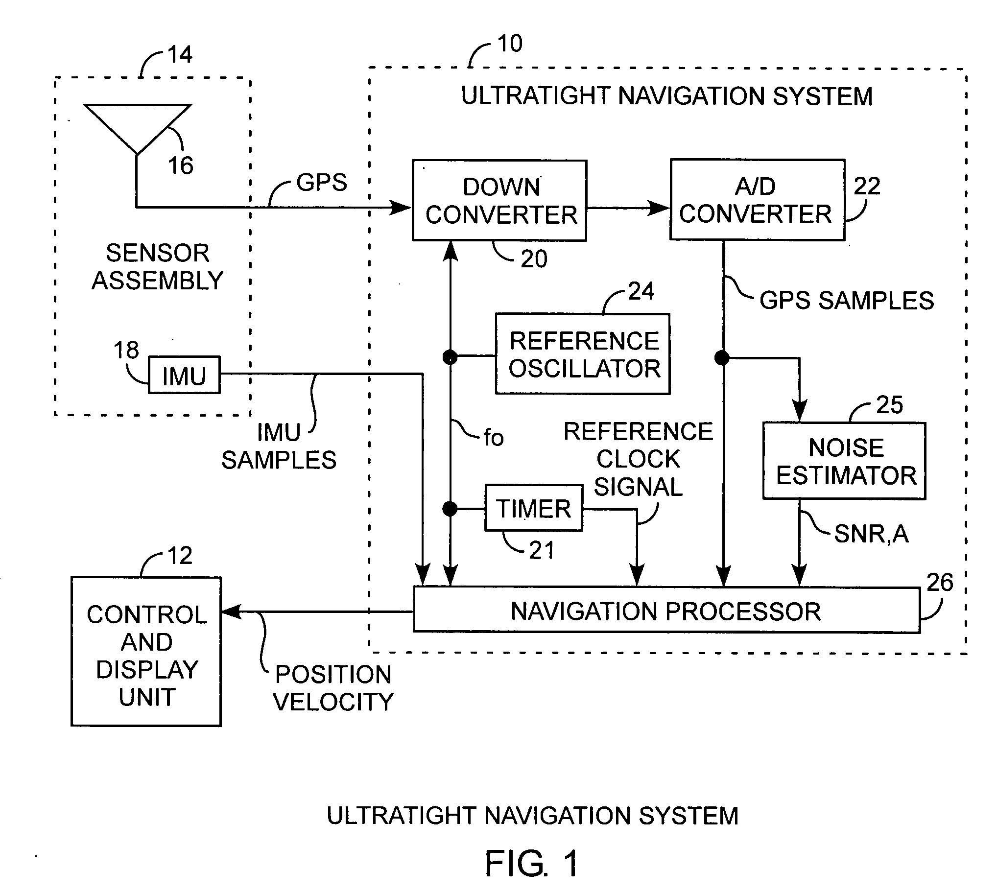
[0022]An embodiment of the invention is described with reference to the figures using reference designations as shown in the figures. Referring to FIG. 1, a global positioning system (GPS) inertial navigation system includes an ultratight navigation system 10 receiving GPS signals and inertial measurement unit samples from a sensor assembly 14. The ultratight navigation system 10 provides position and velocity data to a control and display unit 12. The navigation system 10 functions as a GPS inertial navigation system tracking GPS signals from a plurality of in-view satellites, not shown. The sensor assembly 14 includes an antenna 16 for receiving received GPS signals and communicating the received GPS signals communicated to the navigation system 10. The sensor assembly also includes an inertial measurement unit (IMU) 18 providing the IMU samples that are also communicated to the ultratight navigation system 10. In the preferred form, the IMU 18 may be a microelectromechanical syst...


PUM


Abstract

An observation lock detector block receives I&Q correlations and generates error measurement vectors, each including phase, frequency, code, pseudorange, and covariance residual estimates, and generates validity indicator and confidence indicator vectors, one of which error measurement vectors is an output as a selected error measurement vector with a respective validity indicator and confidence indicator vector, both of which selected vectors are communicated to a navigation solution processor in a ultratightly coupled navigation system for providing improved estimations of a navigation solution, the indicators indicating the usefulness of measurement errors, the prefilter detector block comprising discriminators, sequential filters, observation lock detectors and a measurement selector for selecting measurement vector based on phase, frequency, and code discriminations, the measurement errors being residual estimates that are indicated as valid or invalid for dynamic propagation of the residuals in a navigation receiver for improved performance, especially in low signal-to-noise environments, such as, for use in an ultratight GPS navigation system.

Description

STATEMENT OF GOVERNMENT INTEREST[0001]The invention was made with Government support under contract No. FA8802-04-C-0001 by the Department of the Air Force. The Government has certain rights in the invention.FIELD OF THE INVENTION[0002]The invention relates to the field of ultratight navigation systems. More particularly the present invention is related to GPS ultratight coupling navigation receivers.BACKGROUND OF THE INVENTION[0003]Navigation systems are increasing dependency upon the global positioning system (GPS). The navigation receiver should be able to withstand intentional or unintentional signal interference with robust signal acquisition and tracking. For this reason, inertial navigation systems have been coupled to GPS signal tracking and acquisition systems for improved signal tracking and acquisition of the received signal. Inertial navigation systems (INS) have an inertial measurement unit (IMU) for processing inertial measurements. Coupling navigation data with the GP...

Claims


Application Information

Patent Timeline
IPC IPC(8): H04B1/707
CPCG01S19/47G01S19/26
Inventor LILLO, WALTER E.GOLLAKOTA, MANORAMALUKESH, JOHNDOUGLAS, RANDAL K.
Owner THE AEROSPACE CORPORATION
Why Eureka
Try Eureka