Biometric discrimination device, authentication device, and biometric discrimination method

a biometric and authentication device technology, applied in the field of biometric discrimination system, authentication system, biometric discrimination method, can solve the problems of reducing making “false pretenses”, and restricting the installation site, so as to reduce the possibility of registration, reduce the possibility of restrictions, and increase the accuracy

Inactive Publication Date: 2009-01-15
PANASONIC CORP
View PDF3 Cites 64 Cited by
  • Summary
  • Abstract
  • Description
  • Claims
  • Application Information

AI Technical Summary

Benefits of technology

[0016]With this method, an eye image can be taken while the eye is irradiated with at least two illuminating rays in different radiation directions at different radiation angles to the eye of the subject at the same time. Then, in the at least two different areas in the iris of the taken eye image, ratios between the brightness of the iris and the brightness of the sclera are calculated and compared with each other. Thus, even one eye image taken allows determination of whether the image is of a living body or a forgery at a higher accuracy.
[0017]The present invention can provide a biometric discrimination system, an authentication system, and a biometric discrimination method that has fewer restrictions on the installation site and discriminate an unauthorized eye image using a forgery even when an unauthorized person attempts to pretend to be a registered person using a forgery. Thereby, the present invention can decrease the possibility of registration or authentication of unauthorized eye images.

Problems solved by technology

On the other hand, in the above iris authentication method, there is a possibility that a person attempting to take an illegal action (hereinafter simply referred to as “unauthorized person”) makes “false pretense” to be a registered person.
However, the latter iris authentication method requires placing the subject in an environment with dark ambient light and causing a mydriasis (a biological reaction in which the diameter of the eye increases in dark ambient light) in the eye of the subject beforehand so that the subject has a miosis.
For this reason, in an imaging apparatus using such an iris authentication method, the surrounding of the imaging apparatus must be kept in a dark environment, and thus the installation site is restricted.

Method used


Image

  • Biometric discrimination device, authentication device, and biometric discrimination method
  • Biometric discrimination device, authentication device, and biometric discrimination method
  • Biometric discrimination device, authentication device, and biometric discrimination method

Examples


first exemplary embodiment

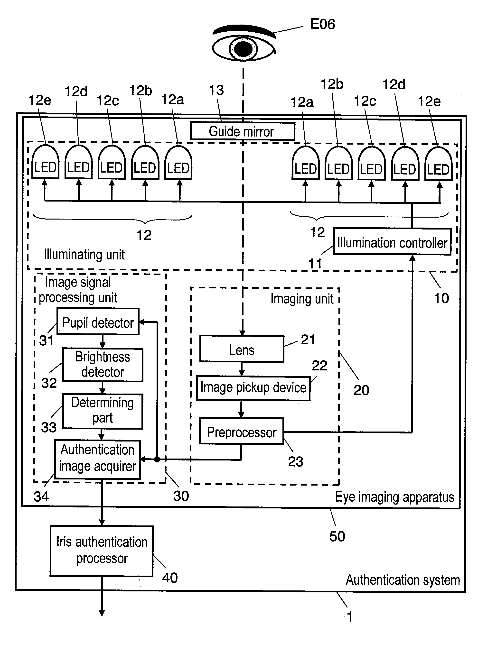
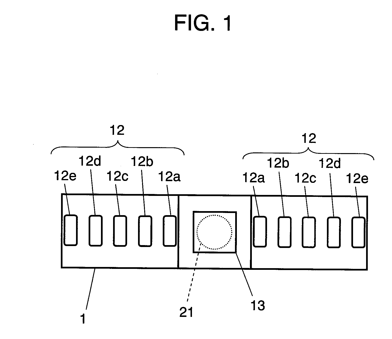
[0093]A description is provided of an authentication system of the first exemplary embodiment of the present invention, with reference to FIG. 1. FIG. 1 is an outline view illustrating an outline of authentication system 1 of the first exemplary embodiment.

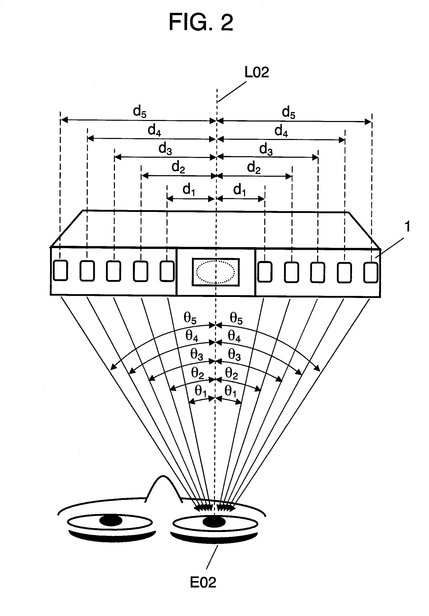
[0094]Authentication system 1 includes the following elements: guide mirror 13 to be used when a subject checks the position of the eye with an image reflected therefrom in imaging the eye of the subject; illuminating LED parts 12 made of known light-emitting devices for emitting near infrared rays; and lens 21 disposed behind guide mirror 13. Illuminating LED parts 12 include five pairs of illuminating LEDs 12a, 12b, 12c, 12d, and 12e disposed symmetrically about the optical axis of lens 21. Each of the five pairs can be switched to emit rays separately. Authentication system 1 takes images including the eye of the subject, i.e. eye images, under illuminating rays emitted from switched illuminating LEDs 12. Thus, in authenticatio...

second exemplary embodiment

[0150]Next, a description is provided of an authentication system of the second exemplary embodiment of the present invention, with reference to the accompanying drawings.

[0151]Described in the first exemplary embodiment is a structure in which illuminating LEDs 12 are made of a plurality of illuminating LEDs 12a, 12b, 12c, 12d, and 12e, and taking eye images under these LEDs switched for light emission provides a plurality of eye images under illuminating rays at different lighting angles to an eye of a subject. However, the plurality of eye images can be taken under illuminating rays at different lighting angles to the eye of the subject not under switched illuminating LEDs 12a, 12b, 12c, 12d, and 12e for light emission but at the distance between the subject and the imaging unit changed at imaging.

[0152]In the second exemplary embodiment, the authentication system is structured so that taking eye images at different distances between the subject and the imaging unit provides at l...

third exemplary embodiment

[0166]Next, a description is provided of an authentication system of the third exemplary embodiment of the present invention, with reference to the accompanying drawings.

[0167]Described in the first exemplary embodiment is a structure in which illuminating LED parts 12 are made of a plurality of illuminating LEDs, and taking eye images under these LEDs switched for light emission provides a plurality of eye images under illuminating rays at different lighting angles to the eye of the subject. However, the plurality of eye images under illuminating rays at different lighting angles to the eye of the subject can be taken not under illuminating LEDs 12 switched for light emission. Instead, the imaging apparatus has at least two light receivers, and the subject makes a relative movement from an imaging position on the optical axis of one of the light receivers to an imaging position on the optical axis of the other one of the light receivers so that an eye image is taken in each positio...


PUM


Abstract

An authentication system includes the following elements: a guide mirror to be used when a subject checks the position of the eye with an image reflected therefrom during imaging the eye of the subject; a lens disposed behind the mirror; and illuminating LEDs that are disposed symmetrically about the optical axis and can be switched for emitting near infrared rays. With this structure, the authentication system takes a plurality of images of the eye of the subject irradiated with illuminating rays from the illuminating LEDs at different lighting angles to the eye of the subject, determines whether the taken eye images are of a living eye or a forgery, and authenticates the iris.

Description

TECHNICAL FIELD[0001]The present invention relates to a biometric discrimination system, authentication system, and biometric discrimination method.BACKGROUND ART[0002]In recent years, various kinds of authentication methods using biometric information have been put to practical use, as a method of personal authentication during access to systems requiring high security, e.g. an entrance and exit control system, and an information system for storing such important information as personal data. The biometric information includes information specific to a subject, such as the fingerprints, iris, fundus blood vessels, features of the face, and vessel patterns of an arm or hand of a human body.[0003]Among these methods, an authentication method using different wrinkle patterns in the iris portion of an eye (hereinafter referred to as “iris authentication method”) is proposed and put to practical use in equipment requiring especially high security, because the method has high reliability...

Claims


Application Information

Patent Timeline
Patent Type & Authority Applications(United States)
IPC IPC(8): G06K9/00G06V10/141
CPCA61B5/117G06K9/2027G06K9/00906G06K9/00604G06V40/19G06V40/45G06V10/141
Inventor TSUKAHARA, SHINICHI
Owner PANASONIC CORP
Why Eureka
Try Eureka