Optical transmission apparatus

a transmission apparatus and optical technology, applied in the direction of transmission monitoring, electromagnetic repeaters, multiplex communication, etc., can solve the problems of deterioration of the optical signal-to-noise ratio (osnr) of light in the receiver input part, deterioration of the dynamic range of light input and the transmission characteristics of the system

Inactive Publication Date: 2009-01-15
FUJITSU LTD
View PDF10 Cites 20 Cited by
  • Summary
  • Abstract
  • Description
  • Claims
  • Application Information

AI Technical Summary

Problems solved by technology

Such a deviation of levels causes deterioration of the optical signal-to-noise ratio (OSNR) of light in a receiver input part, as well as deterioration of the dynamic range of light input and the transmission characteristics of a system.

Method used


Image

  • Optical transmission apparatus
  • Optical transmission apparatus
  • Optical transmission apparatus

Examples


Embodiment Construction

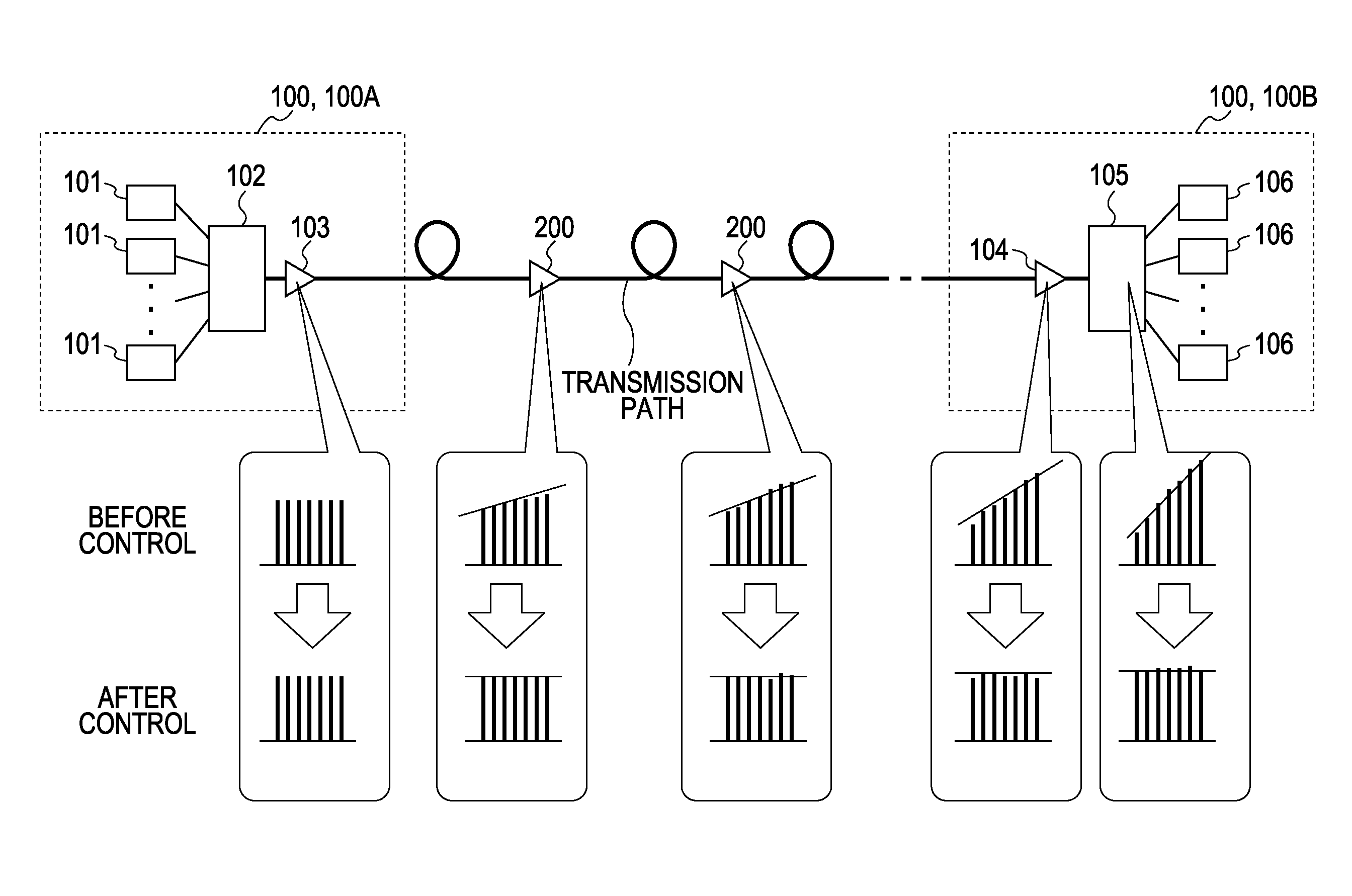
[0025]Reference may now be made in detail to embodiments of the present invention, examples of which are illustrated in the accompanying drawings, wherein like reference numerals refer to like elements throughout. Embodiments of the present invention will be described below with reference to the drawings.

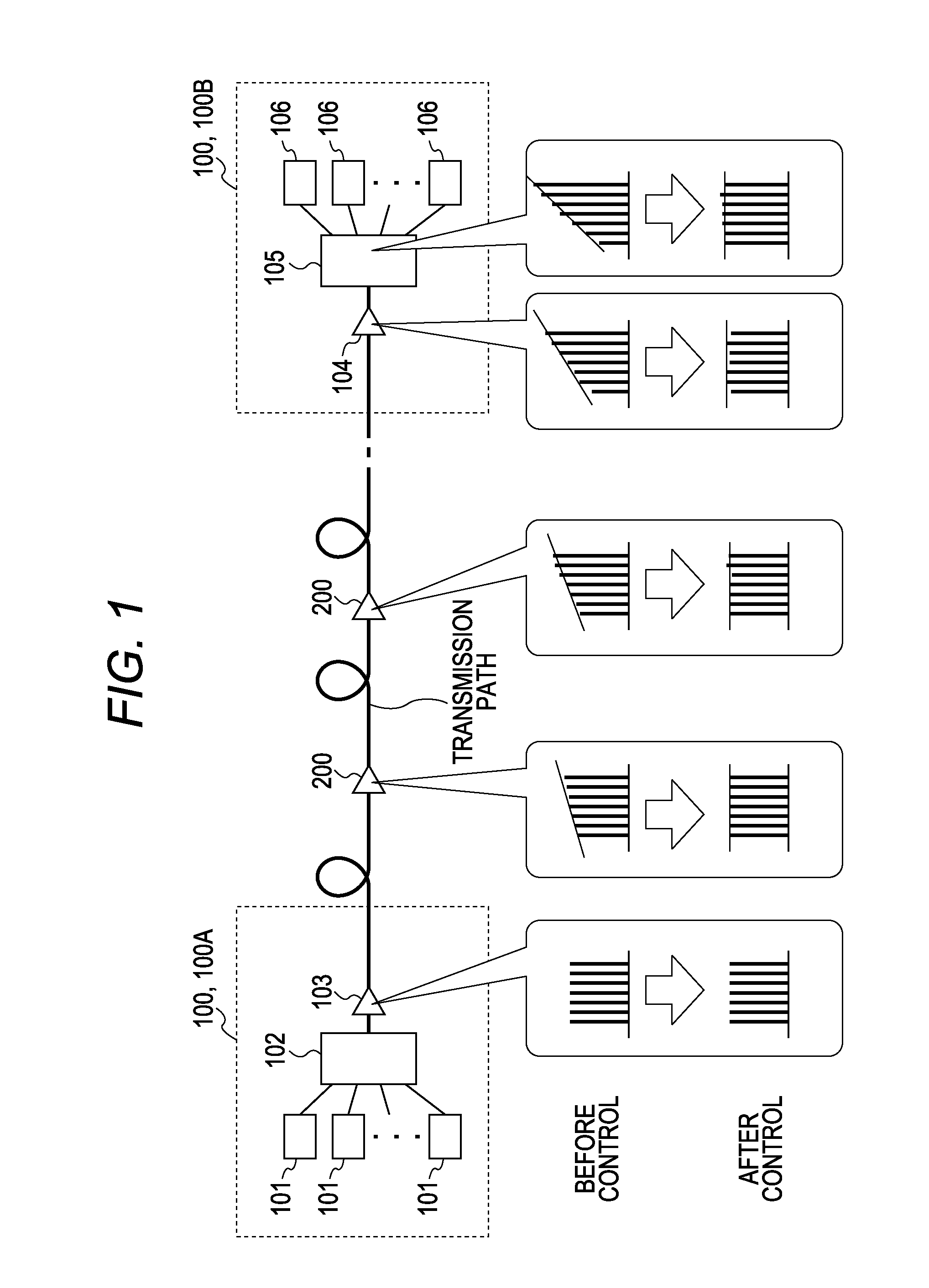
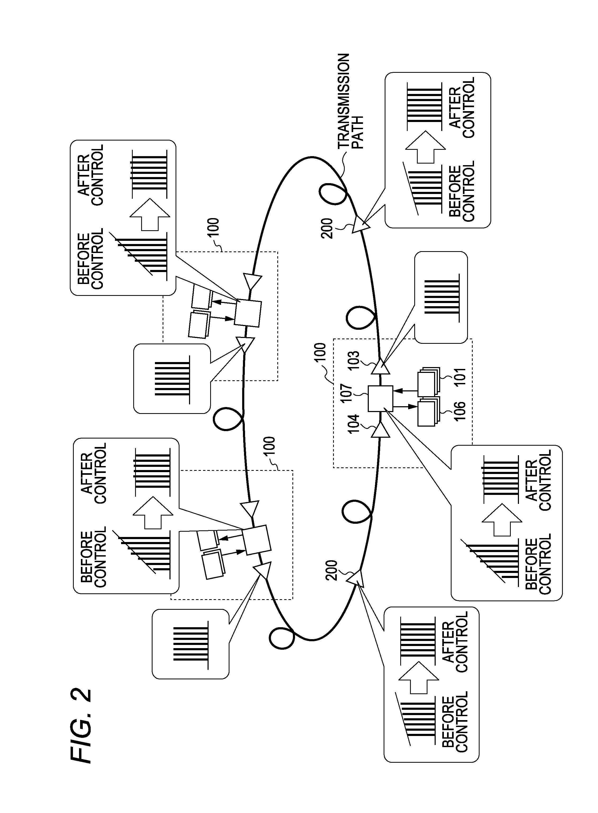
[0026]FIG. 1 is a diagram showing an example of an optical transmission system having a linear configuration and FIG. 2 is a diagram showing an example of an optical transmission system having a ring configuration. The present embodiment is applicable to both the linear configuration and the ring configuration. Incidentally, while an actual optical transmission system has optical transmission paths in both directions, the optical transmission systems in FIGS. 1 and 2 omit an optical transmission path in one direction.

[0027]In FIG. 1, the optical transmission system has one or more relay amplifiers (ILA nodes (optical in-line amplifier equipment)) 200 arranged between an OADM node 10...


PUM


Abstract

An optical transmission apparatus includes a reception part for receiving a wavelength division multiplexed (WDM) signal reached via optical amplifiers; a measuring part for measuring an optical power level of each wavelength of the WDM signal received by the reception part; a determination part for determining whether an amount of tilt of the WDM signal calculated based on measurement results of the measuring part is suitable or not; an operation part for calculating the tilt correction amount to be applied to tilt correction processing performed by the optical amplifiers if the amount of tilt of the WDM signal is not suitable; and a notification part for notifying the optical amplifiers of the tilt correction amount.

Description

CROSS-REFERENCE TO RELATED APPLICATIONS[0001]This application is based upon and claims the benefit of priority to Japanese Patent Application No. 2007-179480, filed on Jul. 9, 2007, the entire contents of which are incorporated herein by reference.BACKGROUND OF THE INVENTION[0002]1. Field of the Invention[0003]The present invention relates to an optical transmission apparatus for receiving a wave division multiplexed (WDM) light or an optical amplifier for relaying light between optical transmission apparatuses.[0004]2. Description of the Related Art[0005]Demands for wave division multiplex (WDM) transmission apparatuses are growing in recent years against the background of increased communication traffic. WDM transmission apparatuses have been actively introduced not only as optical repeating nodes in backbone networks, but also to local networks. Thus many optical add drop multiplexers (OADM) are arranged in a network.[0006]A deviation of levels between wavelengths within a signal...

Claims


Application Information

Patent Timeline
Patent Type & Authority Applications(United States)
IPC IPC(8): H04J14/02H04B10/07H01S3/10H04B10/00H04B10/077H04B10/079H04B10/2507H04B10/2537H04B10/27H04B10/275H04B10/278H04B10/29H04B10/291H04B10/296H04B10/297H04J14/00
CPCH04B10/07955H04B10/294H04J14/0221H04J14/0217H04J14/0204
Inventor UEKI, TAICHIONAKA, MIKI
Owner FUJITSU LTD
Why Eureka
Try Eureka