Image Forming Device and Image Forming Method

Inactive Publication Date: 2009-01-15
KYOCERTA MITA
View PDF2 Cites 12 Cited by
  • Summary
  • Abstract
  • Description
  • Claims
  • Application Information

AI Technical Summary

Benefits of technology

[0033]The above-described image forming device and image forming method enable improvement in the smoothness of the image surface and an increase in gloss without leading to deterioration of the image. As a result, it is possible to obtain a high quality image, i.e., the first object of the present invention can be achieved.
[0034]In addition, it is possible to limit cracking which occurs in the image surface, and to obtain a high quality image with increased gloss, i.e., the second object of the present invention can be achieved.
[0035]By employing the above image forming device and image forming method, the essential vivid hues of deep colors can be obtained, making it particularly ideal for color images.
[0036]Further, when rapidly cooling the toner image, the temperature of the discharged paper can be reduced since the recording medium is also cooled.

Problems solved by technology

However, in contact methods employing heat roller fixing, an offset phenomenon, in which melted toner remains on the heat roller after the recording medium has passed through the heat roller, tends to occur readily.
For example, the production of posters or high quality magazines requires an extremely high level image quality (i.e., high gloss images, etc.) that is difficult to accomplish with images formed using conventional electrophotography methods.
However, when heated toner (melted toner) cools to room temperature, the resins included in the toner shrink during the cooling process.
As a result, a shrink mark can form on the surface of the image, resulting in a deterioration in the smoothness of the image surface and producing an image with reduced gloss.
For this reason, it is difficult to increase gloss further in this device with the toner being completely melted.
Since gloss depends on surface reflectivity, it is therefore not possible to sufficiently improve gloss simply by controlling opacification of the wax layer as disclosed in Reference No. 2.
As a result, it is difficult to obtain the effect of sufficient gloss improvement in solid image areas.
Accordingly, even if the changes in volume and area are prescribed, it is difficult to improve such toner surface properties as image gloss or luster.
As a result, excess electrical power is required, and temperature deviations can occur along the axial direction of the heat roller which is provided to the fixing device.
In addition, warm air around the fixing device is dispersed within the image forming device, causing variation in the sensitivity of the photosensitive body as well as changes in the charge of the developing agent.
Accordingly, this leads to a deterioration in the image.

Method used


Image

  • Image Forming Device and Image Forming Method
  • Image Forming Device and Image Forming Method
  • Image Forming Device and Image Forming Method

Examples


examples 1 to 6

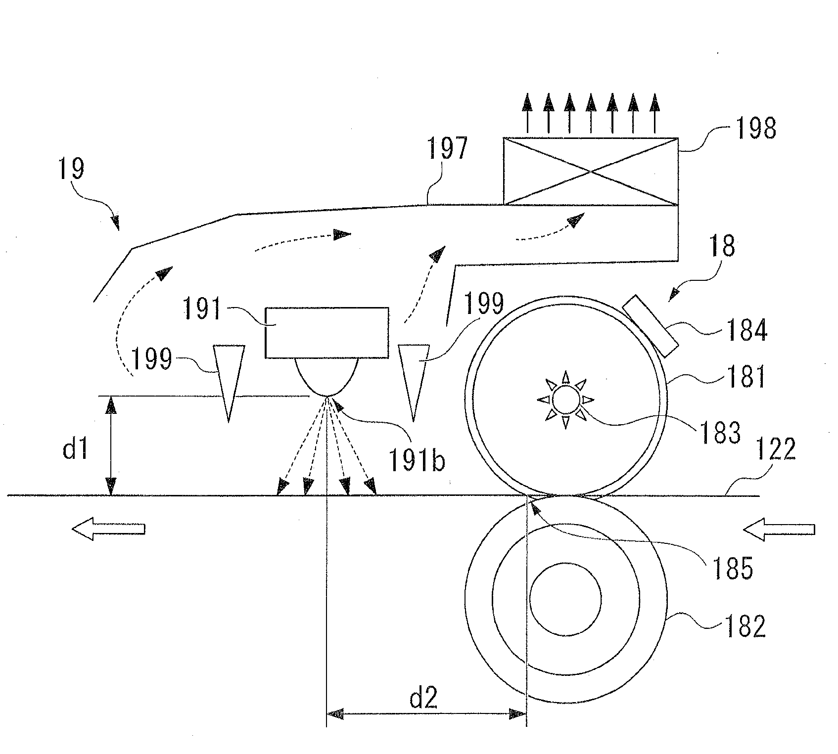
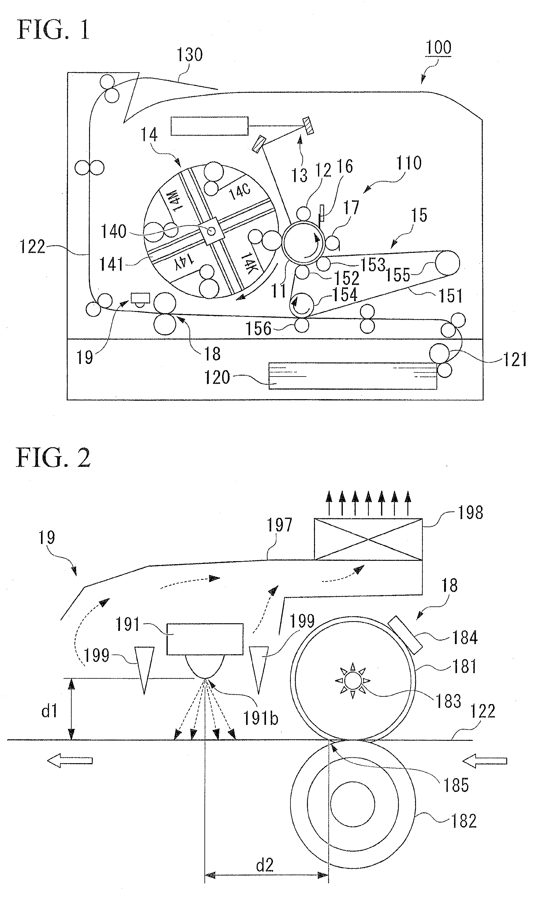
[0105]An image forming device having the structure shown in FIGS. 1 to 3 was employed, and a toner obtained in advance was housed in the developer. The design of the fixing unit 18 and the cooling unit 19 are as follows.

(Fixing Unit)

[0106]For the fixing roller 181, a design was employed in which 200 μm thick silicon rubber having a hardness of 5 (JIS-A) was coated to the surface of a 1.0 mm thick aluminum tube having an outer diameter of φ30 mm, after which a 30 μm thick PFA (a copolymer of tetrafluoroethylene and perfluoralkoxyethylene) tube was adhered via a primer to the surface of the above coated aluminum tube. A halogen heat lamp 183 was disposed inside the fixing roller 181, and lighting of the lamp was controlled so that the surface temperature of the fixing roller was a constant 170° C. according to a thermistor 184 that was in contact with the surface of the fixing roller 181.

[0107]For the pressure roller 182, a solid iron rod having a core with an outer diameter of φ18 mm...

examples 7 to 10

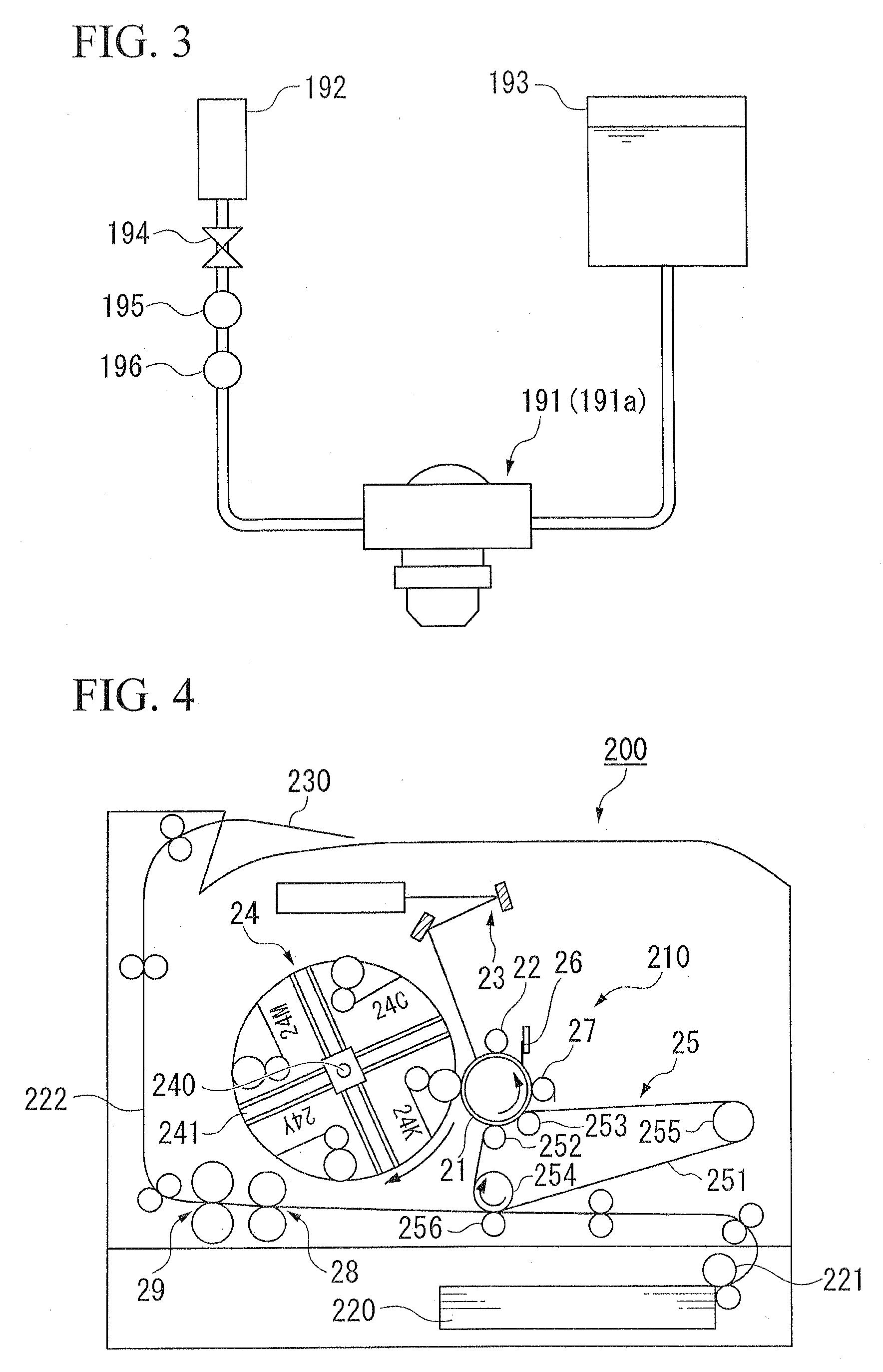
[0174]For the image forming device, the design shown in FIGS. 4 and 5 was employed after appropriate modification to suit the developing agent. For the developing agent, the previously obtained toner A (cyan toner) was employed and was housed in the developer container. Note that the design of the fixing unit 28 and the cooling unit 29 is as follows below.

(Fixing Unit)

[0175]For the fixing roller 281, a design was employed in which 200 μm thick silicon rubber having a hardness of 5 (JIS-A) was coated to the surface of a 1.0 mm thick aluminum tube having an outer diameter of φ30 mm, after which a 30 μm thick PFA (a copolymer of tetrafluoroethylene and perfluoralkoxyethylene) tube was adhered via a primer to the surface of the above coated aluminum pipe. A halogen heat lamp 283 was disposed inside the fixing roller 281, and lighting of the lamp was controlled so that the surface temperature of the fixing roller was a constant 170° C. with use of a thermistor 284 that was in contact wit...

example 12

[0185]With the exception of employing a two component developing agent produced using toner B as the developing agent, image formation was carried out in the same manner as in Example 9, and evaluated. These results are shown in Table 2.


PUM


Abstract

An image forming device including: a fixing unit that fixes a toner image formed on a recording medium by heating the toner image to a temperature that is higher than the softening point of a toner that forms the toner image; and a cooling unit that cools the fixed toner image from a temperature that is higher than the softening point of the toner, to a temperature that is lower than the softening point of the toner, at a predetermined cooling speed.

Description

BACKGROUND OF THE INVENTION[0001]Priority is claimed on Japanese Patent Application No. 2007-183364, filed on Jul. 12, 2007, Japanese Patent Application No. 2007-183365, filed on Jul. 12, 2007, and Japanese Patent Application No. 2007-183366, filed on Jul. 12, 2007, the contents of which are incorporated herein by reference.[0002]1. Field of the Invention[0003]The present invention relates to an image forming device in which a toner image is formed on a recording medium using an electrophotography, for example, and the image is formed by fixing the toner. The present invention further relates to an image forming method.[0004]2. Description of Related Art[0005]In an image forming device employing electrophotography, for example, a toner image formed on a photosensitive body is transferred to an intermediate transfer body, after which the toner image is transferred to a paper sheet (the aforementioned recording medium) which is passes between the intermediate transfer body and a trans...

Claims


Application Information

Patent Timeline
IPC IPC(8): G03G21/20
CPCG03G2221/1645G03G15/6573G03G15/2017
Inventor HONDA, MITSUNOBU
Owner KYOCERTA MITA
Why Eureka
Try Eureka