Device and method for adjusting angle-of-attack of wind blades in lift-type vertical axis wind turbine

Inactive Publication Date: 2009-01-15
YAN QIANG
View PDF6 Cites 17 Cited by
  • Summary
  • Abstract
  • Description
  • Claims
  • Application Information

AI Technical Summary

Benefits of technology

[0012]This invention relates to a lift-type rotor. Taking into consideration the deficiency of the above existing technology, this invention overcomes the design defects of existing vertical axis wind turbine and puts forth an angle-of-attack adjusting device for blades which can effectively lower the starting wind speed of vertical axis wind turbine and increase its wind energy utilization ratio by adjusting the angle of attack of the blades.
[0036]The device of this invention can be used to adjust the blade's angle of attack, so that the blade can rotate in a controlled way relative to the cantilever support wing. As shown in FIG. 2, the rotating angle α can be adjusted, so the blade's angle of attack δ relative to the wind direction can always be within the set range. In this way, when a blade is at any position on the circumference, i.e., an azimuth angle β of 0-360 degrees, no moment of resistance, but moment of rotation, is produced, thus increasing the wind energy utilization ratio of the vertical axis wind turbine.
[0039]Compared with wind turbines adopting conventional technology (i.e., wherein each blade has a fixed rotating angle), the device for this invention can guarantee that the blades' angles of attack for different positions on the circumference are within optimized ranges so that the blades can produce a driving moment at different positions, thus increasing the wind energy utilization ratio.
[0041]During rotation, the blade angle-of-attack adjusting device for this invention does not require any extra energy consumption except for some energy consumption required to adjust wind rotor's position by starting motor to adapt to the wind direction change.

Problems solved by technology

Therefore, it is unavoidable that conventionally blades are fixed on the wind rotor's cantilever support wing.

Method used


Image

  • Device and method for adjusting angle-of-attack of wind blades in lift-type vertical axis wind turbine
  • Device and method for adjusting angle-of-attack of wind blades in lift-type vertical axis wind turbine
  • Device and method for adjusting angle-of-attack of wind blades in lift-type vertical axis wind turbine

Examples


example 1

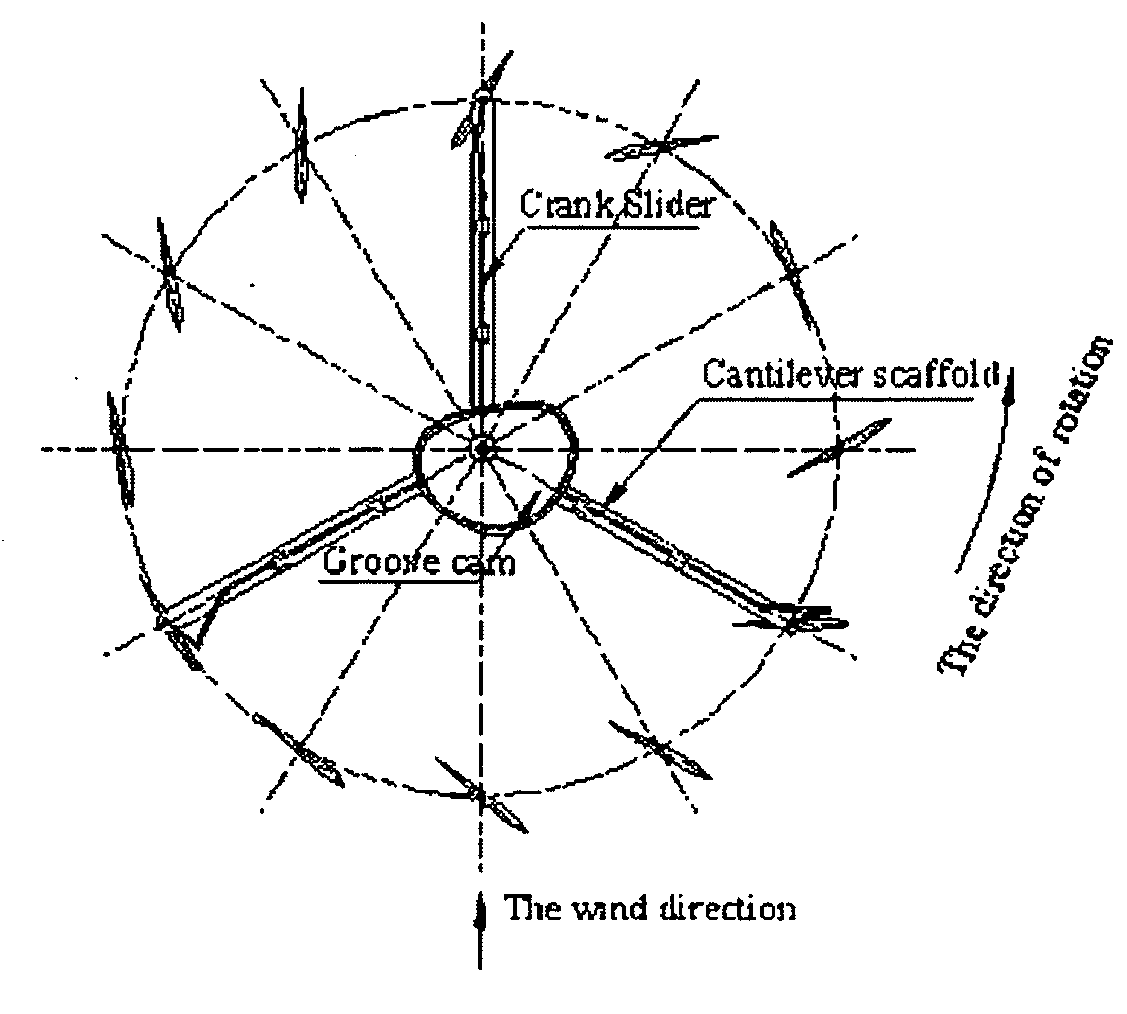
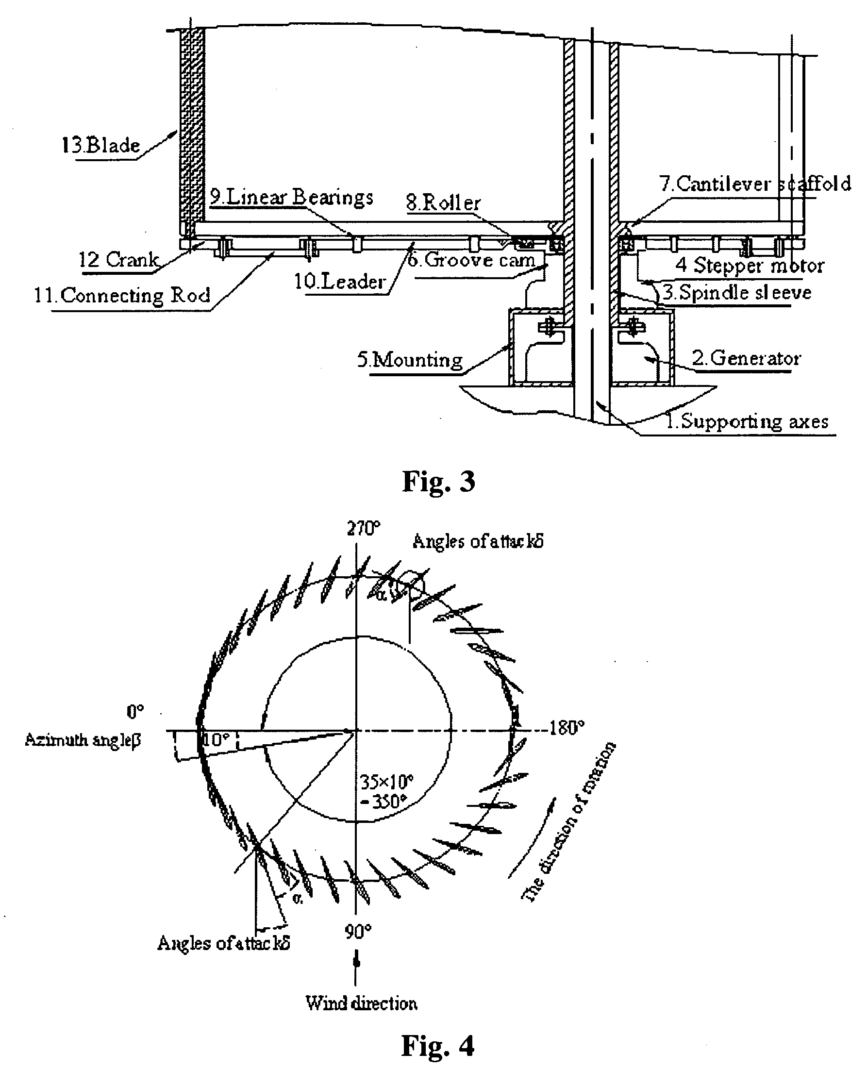
[0053]As shown in FIG. 3, the wind rotor of vertical axis wind turbine 2 is supported by the support frame 5. The support axis 1 is inside the vertical axis wind turbine 2. There is a spindle sleeve 3 outside the support axis 1. There are also a wind indicator, a step motor 4 and a control device for step motor. Wind indicator is used to inspect the change of the wind direction and provides wind direction signal to the control device for the step motor. Because the wind indicator of this device and the control device for the step motor are one part of the control device for the wind turbine, they are not shown in the figure. The step motor 4 adopts a hollow step motor for direct adjustment. The rotors of the motor are hollow so that wind rotor's spindle sleeve 3 can pass through. The step motor 4 is fixed on the fixed support below the step motor. The flange on its rotor is connected to grooved cam 6, so it can drive the grooved cam to rotate.

[0054]In this example, the blade angle-o...

example 2

[0062]As shown in FIG. 8, the gear and the gear rack are connected to the cam and blades. Other devices are the same as those in Example 1. The bar mechanism and the slider mechanism are replaced with gear and the gear rack structure as the driving device. The grooved cam mechanism realizes the adjustment of the blade's angle of attack together with the gear and the gear rack. The optimized range of angle of attack δ is the same as that when a grooved cam mechanism is used together with a slider mechanism.


PUM


Abstract

A device for adjusting an angle-of-attack (δ) of blades in a lift-type vertical axis turbine comprising a vertical rotating axis, a rotatable cantilever support wing fixed on the vertical rotating axis, a wind rotor comprising a plurality of blades mounted on the cantilever support wing, at least one cam disposed along an axial direction of the vertical rotating axis, the axial direction of the cam being parallel to the rotating axis, and for any point in a contour line of the cam, the angle of attack δ being set according to the following formula: δ=β−α, wherein δ is the angle of attack; β is an azimuth angle; α is a rotating angle for blades; and δ, β, and α are preset values.

Description

CROSS-REFERENCE TO RELATED APPLICATIONS[0001]This application is a continuation of International Patent Application No. PCT / CN2007 / 000458, with an international filing date of Feb. 9, 2007, designating the United States, now pending, which is based on Chinese Patent Application No. 200610023892.2, filed Feb. 15, 2006. The contents of all of these specifications are incorporated herein by reference.BACKGROUND OF THE INVENTION[0002]1. Field of the Invention[0003]This invention relates to vertical axis wind turbine and in particular, refers to a device and method for adjusting angle-of-attack of blades which can effectively lower the starting wind speed and increase the wind energy utilization ratio.[0004]2. Description of the Related Art[0005]In order to make better use of wind energy, various wind generating devices of different structure and form have been developed for a long time. Depending on the position of the rotating axis, wind turbines are divided into horizontal axis wind t...

Claims


Application Information

Patent Timeline
IPC IPC(8): F03D3/00F03D7/06
CPCF03D3/067F03D3/068F05B2240/211Y02E10/74F05B2260/503F05B2260/506Y02E10/721F05B2260/50Y02E10/72Y10S415/907F03D7/06
Inventor YAN, QIANG
Owner YAN QIANG
Why Eureka
Try Eureka