Method for producing optical film

a technology of optical film and film layer, which is applied in the direction of instruments, coatings, chemistry apparatuses and processes, etc., can solve the problems of inability to carry out rubbing treatment in a stable condition and inability to use a method, and achieve uniform optical characteristics, low cost, and the effect of reducing the effect of rubbing

Inactive Publication Date: 2009-01-15
NITTO DENKO CORP
View PDF4 Cites 8 Cited by
  • Summary
  • Abstract
  • Description
  • Claims
  • Application Information

AI Technical Summary

Benefits of technology

[0027]Moreover, the thickness of the above conveyer belt is preferably 0.5 mm to 2.0 mm (more preferably 0.7 to 1.5 mm) not only to prevent the belt from loosing easily but also to impart flexibility to the belt.
[0028]The method for producing an optical film according to the present invention makes it possible to produce an optical film having uniform optical characteristics at low costs.

Problems solved by technology

However, in the case where using a lengthy TAC film as a base material, rubbing treatment is continuously carried out by a roll-to-roll system, this may be a cause of the blocking (a phenomenon that base materials are stuck among them without the presence of an optical interface) of the base material put into a state wound around a roll prior to the rubbing treatment.
Therefore, there is the problem that even if the base material is rubbed, the blocked part differs in orientation properties from the other part, so that domains arise in the liquid crystalline molecule and there is therefore the case where uniform orientation state cannot be obtained.
Also, there is the problem that if the pushing amount is made to be excessively large, the rubbing treatment cannot be carried out in a stable condition because of, for example, the influence of a loosened conveyer belt.
Also, this method is not practical because it is required to install the rubbing roll and backup roll with high positional accuracy in order to increase the pushing amount and carry out rubbing treatment in a stable condition.

Method used


Image

  • Method for producing optical film
  • Method for producing optical film
  • Method for producing optical film

Examples


example 1-1

(1) Rubbing Treatment

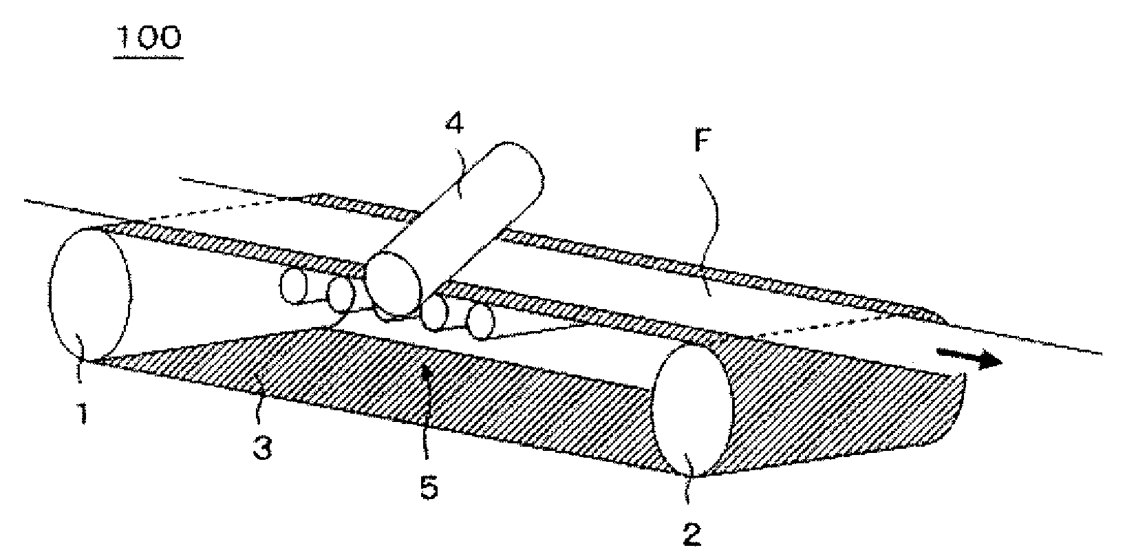
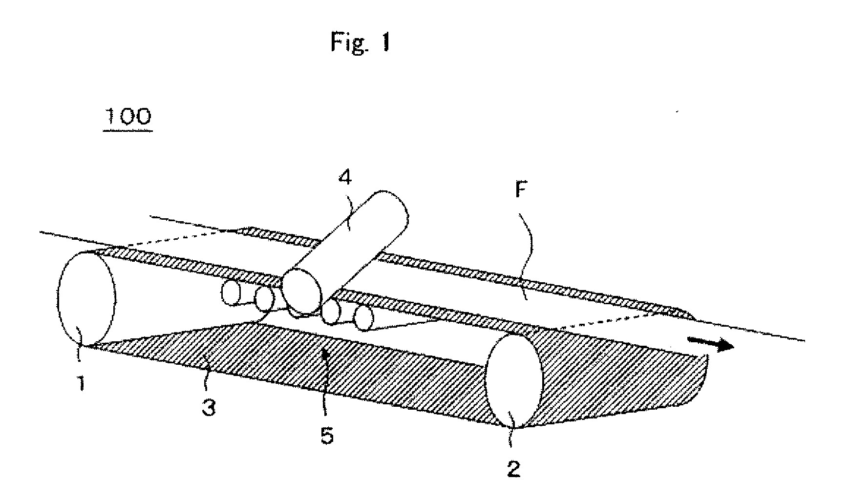
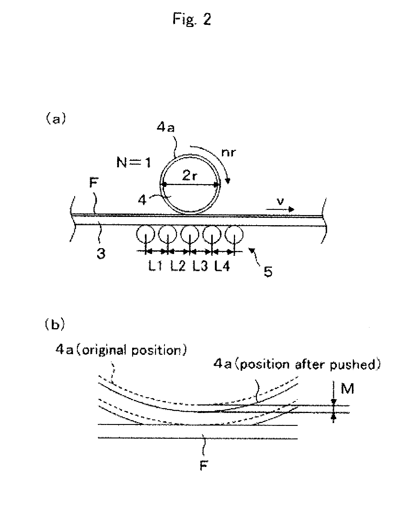
[0064]A rubbing treatment apparatus 100 shown in FIG. 1 and FIG. 2 was used to give rubbing treatment to the surface of a 40 μm-thick saponified triacetyl cellulose film. The mirror finished surface of the conveyer belt 3 had Ra=0.01 μm, the outside diameters of the drive rolls 1 and 2 were respectively 550 mm, the conveying speed of the film was 5 m / min and the intervals L1-L4 between the axes of adjacent backup rolls 5 were all 80 mm. Also, the radius of the rubbing roll 4 (including a raised fabric 4a) was 76.89 mm and a raised fabric made of rayon was wound as the rubbing roll 4 upon use. The rotating axis of the rubbing roll 4 was slanted at an angle of 24.3° with respect to the conveying direction of the film, the number of rotations of the rubbing roll 4 was 1500 rpm and the pushing amount was 0.3 mm. The rubbing strength in this condition was 2609 mm.

(2) Preparation of a Coating Solution Containing a Liquid Crystal Compound

[0065]0.03 g of an optical poly...

example 1-2

[0067]A retardation film was manufactured according to Example 1-1 except that the pushing amount of the rubbing roll 4 was set to 0.4 mm (the rubbing strength at this time was 3479 mm).

example 1-3

[0068]A retardation film was manufactured according to Example 1-1 except that the pushing amount of the rubbing roll 4 was set to 0.5 mm (the rubbing strength at this time was 4349 mm).


PUM

PropertyMeasurementUnit
diameteraaaaaaaaaa
diameteraaaaaaaaaa
thicknessaaaaaaaaaa

Abstract

This invention provides a method for producing an optical film, the method comprising a rubbing treatment step of rubbing the surface of a lengthy plastic film F with a rubbing roll 4 obtained by winding a raised fabric 4a, an application step of applying a liquid crystalline molecule to the surface of the plastic film processed through said rubbing treatment step and a fixing step of fixing said applied liquid crystalline molecule. In the rubbing treatment step, the lengthy plastic film is supported and conveyed by a conveyer belt 3 having a metal surface, and plural backup rolls 5 which support the underside of the conveyer belt supporting the plastic film are disposed opposite to said rubbing roll, to set a rubbing strength RS defined by the following equation (1) to 2600 mm or more (more preferably 3400 mm or more).

Description

TECHNICAL FIELD[0001]The present invention relates to a method for producing an optical film used for optical compensation and antireflection in a liquid crystal display device and the like, and particularly, to a method for producing an optical film having uniform optical characteristics at low costs.BACKGROUND ART[0002]Various optical elements produced by applying a liquid crystal material to the surface of a base material and by orientating the liquid crystal have been known. In a process of manufacturing such optical elements, rubbing treatment in which the surface of the base material is rubbed in one direction with a raised fabric is usually carried out to orientate the liquid crystal material on the surface of the base material. When the optical element is, for example, a liquid crystal cell, a glass substrate which is the base material is subjected to rubbing treatment as a unit. However, in the case of an optical element (optical film) using a plastic film as the base mater...

Claims


Application Information

Patent Timeline
Patent Type & Authority Applications(United States)
IPC IPC(8): B05D3/12B05D5/00
CPCC08J7/18C08J2301/12G02F1/133784C09K2019/0448G02F1/133305C09K19/2007G02F1/13G02F1/1337
Inventor HADA, KAZUYAKAWAMOTO, IKUOYONEZAWA, HIDEYUKIKAMIJOU, TAKASHIUMEMOTO, SEIJI
Owner NITTO DENKO CORP
Why Eureka
Try Eureka