
Medical tool arrangement

a technology of hand-held casings and tools, applied in the field of medical tool arrangements, can solve the problems of increasing the size of the vacuum unit, increasing the complexity of interventions, and needing additional manipulation or action of the physician, so as to reduce the dimensions and weight of the hand-held casings, and the effect of reducing the dimensions and weigh

Inactive Publication Date: 2009-01-15
JANSSENS JAAK PH
View PDF5 Cites 42 Cited by
  • Summary
  • Abstract
  • Description
  • Claims
  • Application Information

AI Technical Summary

Benefits of technology

[0006]It is an advantage of the present invention that consecutive tissue samples may be taken without the need of removing the biopsy needle assembly after each sample been taken. It is as well an advantage of the present invention that EMI interferences, e.g. from the driving motors may be avoided.
[0007]It is also an advantage of the present invention that the medical tool arrangement, optionally a medical tool arrangement for taking tissue sample, may be provided in a hand-held casing, which dimensions and weight of the hand-held casing may be reduced. The reduced dimensions and weight make the hand-held casing useful for handsome handling, especially in combination with other apparatuses used during the medical manipulation, e.g. scanning equipment such as MRI scanners which are used in conjunction with the medical tool arrangement, such as a medical tool arrangement comprising one or more biopsy needles for taking tissue sample, to ensure accurate placing of the medical tools.
[0008]According to a first aspect of the present invention, a medical tool arrangement comprising a hand-held casing is provided. The hand-held casing comprises a tool assembly having a plurality of tools. The hand-held casing further comprises a driving mechanism for moving the plurality of tools independently of each other. The medical tool arrangement is for use with a mechanical energy source remote from the hand-held casing. The mechanical energy source is couplable to the driving mechanism of the hand-held casing by means of at least a first and a second mechanical energy transferring means. At least one of the first and second mechanical energy transferring means has a length and an axial direction and comprises an energy transferring medium suitable for transferring mechanical energy by making a translational movement longitudinally along its axial direction.
[0009]The hand-held casing may provide a hand held device, comprising a tool assembly having a plurality of tools and a driving mechanism for moving the plurality of tools independently of each other.
[0010]A translational movement is a movement backwards and / or forwards made by the energy transferring medium within the mechanical energy transferring means longitudinally along the axial direction of the mechanical energy transferring means.
[0011]According to some embodiments, the plurality of tools may be arranged concentrically.

Problems solved by technology

This requires significant size increase of the vacuum unit.
It is also a disadvantage of the presently known vacuum assisted biopsy needle assemblies that an additional manipulation or action of the physician is needed in order to activate the vacuum at the end of the biopsy needle.
As medical interventions become more and more complex, such additional action to activate the vacuum may easily be overlooked.
It is as well a disadvantage that most often, when a physician is to take several consecutive tissue samples, the biopsy needle assembly is to be brought in as many times as tissue samples are needed.
This obviously causes discomfort for both patient and physician, may result in more damage caused to the patient by the consecutive penetration of the body and may cause seeding of diseased, e.g. tumour cells along the extraction pathway.
It is also a disadvantage of presently known assemblies, that driving means such as motors are located in the hand hold device, which may cause interference, such as EMI interference, with the other apparatuses used during the medical manipulation, e.g. scanning equipment such as MRI scanners which are used in conjunction with the biopsy needle to ensure accurate placing of the needle tip.

Method used


Image

  • Medical tool arrangement
  • Medical tool arrangement
  • Medical tool arrangement

Examples


Embodiment Construction

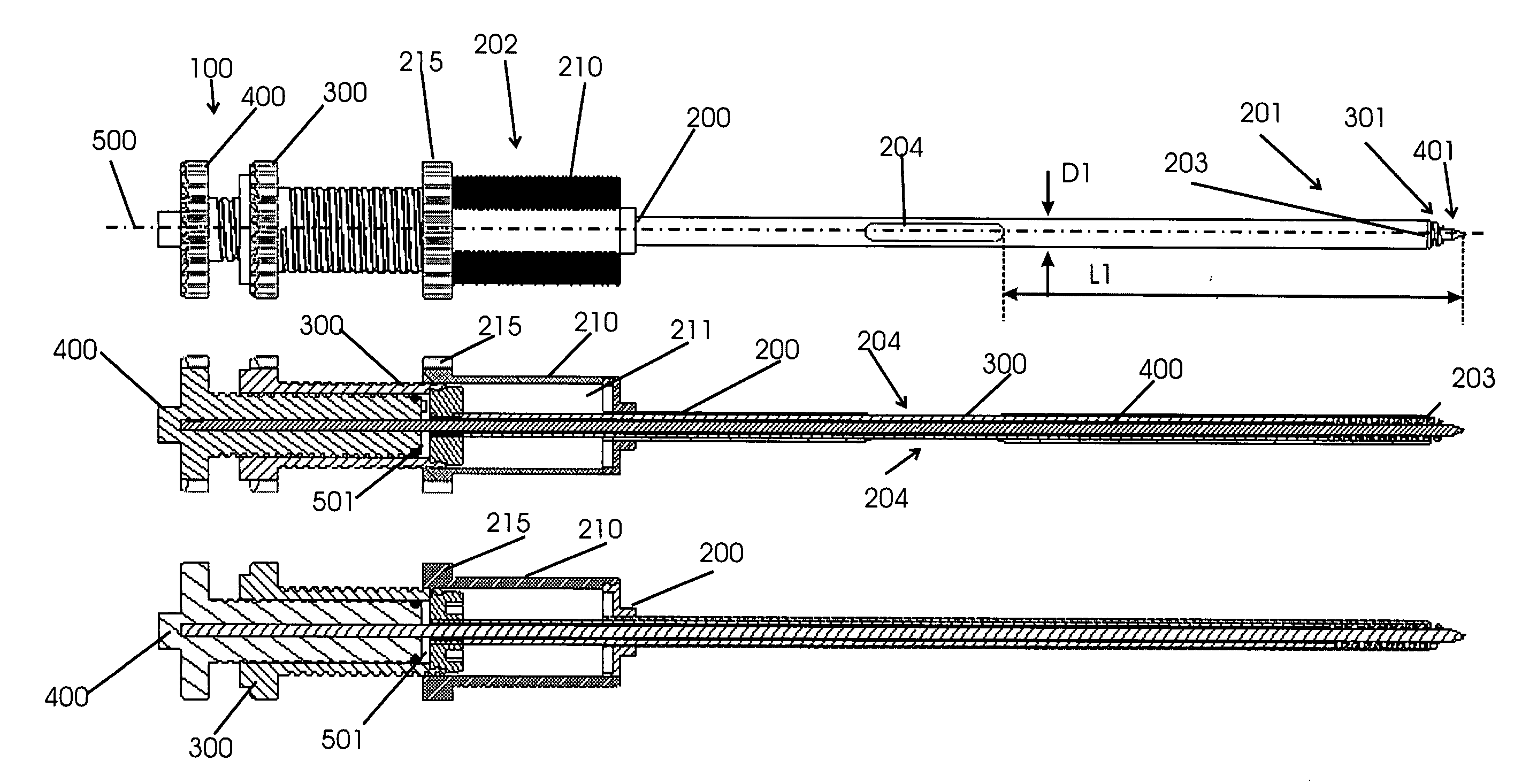
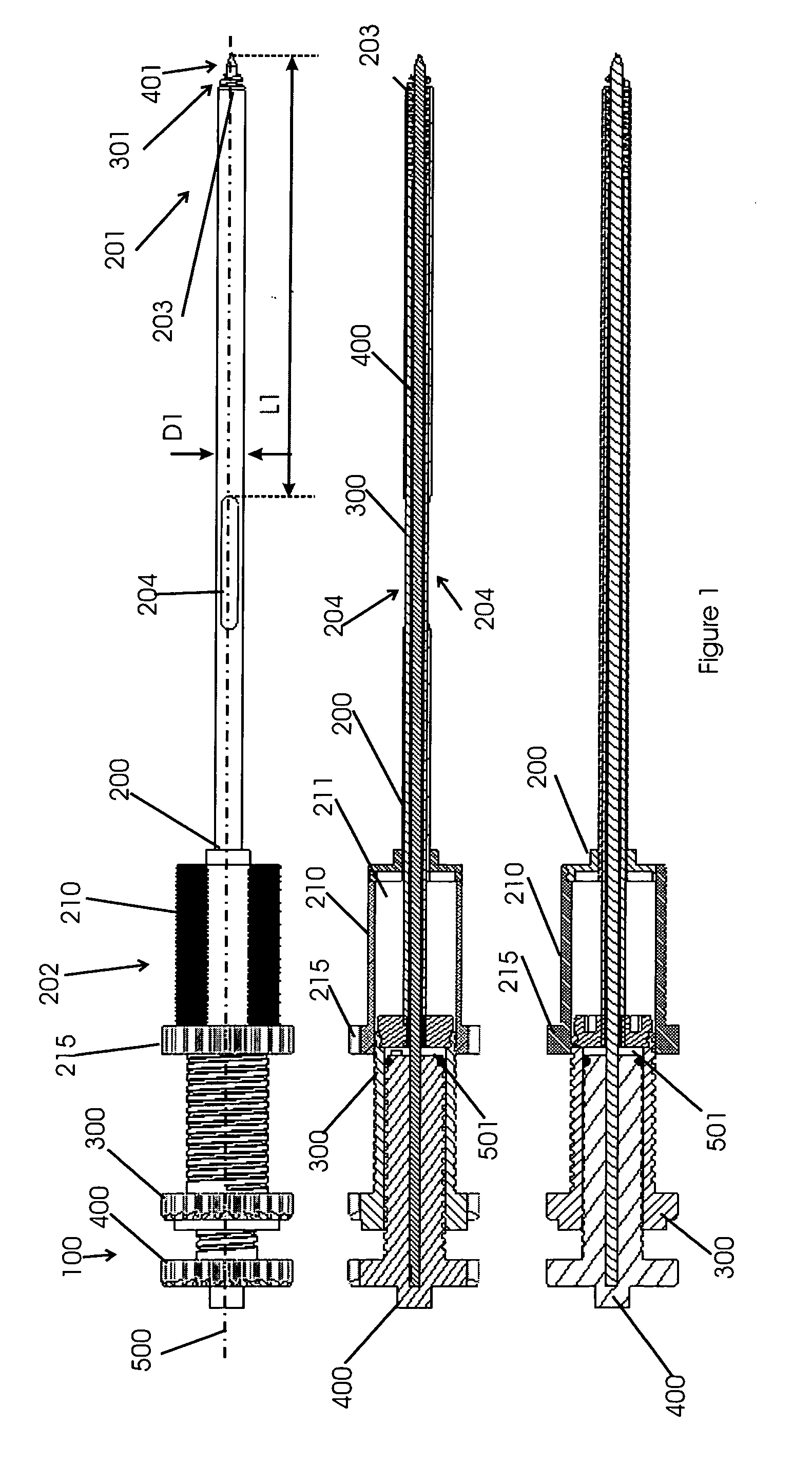
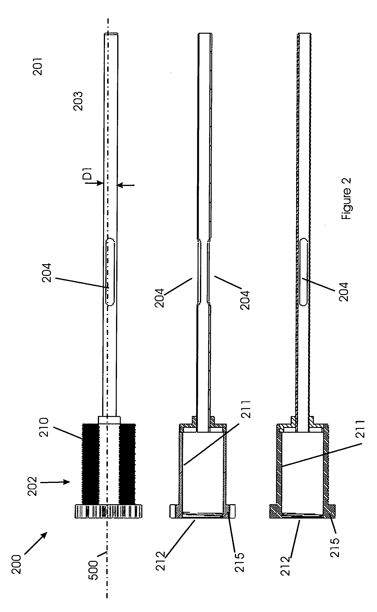
[0088]The present invention will be described with respect to particular embodiments and with reference to certain drawings but the invention is not limited thereto but only by the claims. The drawings described are only schematic and are non-limiting. In the drawings, the size of some of the elements may be exaggerated and not drawn on scale for illustrative purposes. The dimensions and the relative dimensions do not correspond to actual reductions to practice of the invention.

[0089]Furthermore, the terms first, second, third and the like in the description and in the claims, are used for distinguishing between similar elements and not necessarily for describing a sequence, either temporally, spatially, in ranking or in any other manner. It is to be understood that the terms so used are interchangeable under appropriate circumstances and that the embodiments of the invention described herein are capable of operation in other sequences than described or illustrated herein.

[0090]More...


PUM


Abstract

A medical tool arrangement according to the present invention comprises a hand-held casing. The hand-held casing comprises a tool assembly having a plurality of tools. The hand-held casing further comprises a driving mechanism for moving the plurality of tools independently of each other. The medical tool arrangement is for use with a mechanical energy source remote from the hand-held casing. The mechanical energy source is couplable to the driving mechanism of the hand-held casing by means of at least a first and a second mechanical energy transferring means. At least one of the first, and second mechanical energy transferring means has a length and an axial direction and comprises an energy transferring medium suitable for transferring mechanical energy by making a translational movement longitudinally along its axial direction.

Description

TECHNICAL FIELD OF THE INVENTION[0001]The present invention relates to medical tool arrangements comprising a tool assembly having a plurality of tools. The medical tool arrangements may be medical tool arrangements for sampling tissue from human or animal body, using biopsy needles or needle assemblies.BACKGROUND OF THE INVENTION[0002]Biopsy needle assemblies are already well known in different forms. As an example, US2003 / 0114773A1 describes a biopsy needle assembly comprising an outer cannula for insertion in a tissue of which the front end has a cutting edge for cutting the tissue sample. The biopsy needle assembly comprises further a hollow biopsy needle located inside and coaxially with the cannula, at the front end being provided with a tissue receiving means, such as a helical screw. The tissue receiving means cooperates with the cutting edge of cannula for receiving cut tissue sample. The biopsy needle assembly further can comprise an inner needle or localisation needle, ha...

Claims


Application Information

Patent Timeline
Patent Type & Authority Applications(United States)
IPC IPC(8): A61B10/00
CPCA61B10/0266A61B10/0275A61B2017/00544A61B2010/0225A61B2017/00539A61B10/0283
Inventor JANSSENS, JAAK PH.
Owner JANSSENS JAAK PH
Features
  • Generate Ideas
  • Intellectual Property
  • Life Sciences
  • Materials
  • Tech Scout
  • Unparalleled Data Quality
  • Higher Quality Content
  • 60% Fewer Hallucinations
Learn More