Multi-axis connection and methods for internal spinal stabilizers

a stabilizer and multi-axis technology, applied in the field of multi-axis connection and methods for internal spinal stabilizers, can solve the problems of increasing the instability of the spine, challenging the treatment field of damaged or diseased intervertebral disks,

Active Publication Date: 2009-01-15
PERUMALA HLDG LLC A BELIZE LLC
View PDF12 Cites 80 Cited by
  • Summary
  • Abstract
  • Description
  • Claims
  • Application Information

AI Technical Summary

Benefits of technology

[0011]The invention also contemplates a spinal stabilizer including such a multi-axis connection. The spinal stabilizer comprises a plate adapted to be affixed to a vertebra and having a plurality of holes formed therein, each hole defining an aperture, an opening, and a central portion between the aperture and the opening. The screw is comprised of a threaded shank and a threaded head, the shank of the screw extending into the body of the vertebra when the screw is rotated relative to the plate so that the thread on the head of the screw pulls the head of the screw through the aperture and into the central portion of the hole, thereby providing effective transfer of the load from the patient's spinal column to the spinal stabilizer regardless of the angle at which the screw is oriented relative to the plane defined by the aperture of the hole in the plate and locking the screw in the plate at the same time.
[0013]The present invention also provides a method of transferring load from the vertebrae of a patient to the plate of a spinal stabilizer comprising the steps of approximating a plate to the surfaces of the vertebrae to be stabilized, driving a screw through a hole in the plate and into the vertebrae until the head of the screw contacts the plate at the margin of an aperture, the aperture, an opening, and a central portion between the aperture and opening defining the hole in the plate, the aperture and the opening being smaller in dimension than the head of the screw. After the screw contacts the plate at the margin of the aperture, the screw is rotated (relative to the plate) approximately one turn so that a screw thread formed on the head of the screw bites into the material comprising the plate at the margin of the aperture and pulls the head of the screw through the aperture and into the central portion of the hole in the plate. In the preferred embodiment, the central portion of the hole is larger in dimension than the head of the screw so that the screw can be positioned so as to extend from the plate at any of a plurality of angles relative to the plane defined by the aperture of the hole in the plate and the head of the screw can move freely in the central portion of the hole to accommodate the particular angle required at the interface between the screw and the plate while still being retained within the hole by the smaller diameters of the opening and the aperture of the hole.

Problems solved by technology

Treatment of a damaged or diseased intervertebral disk continues to be a challenging field of medicine.
However, removing the disk increases the instability of the spine.
However, depending upon the particular pathology of the patient, partial diskectomy and fusion is not always indicated and problems relating to the failure of the bone chips to fuse and other complications of this surgery are well documented.

Method used


Image

  • Multi-axis connection and methods for internal spinal stabilizers
  • Multi-axis connection and methods for internal spinal stabilizers
  • Multi-axis connection and methods for internal spinal stabilizers

Examples


Embodiment Construction

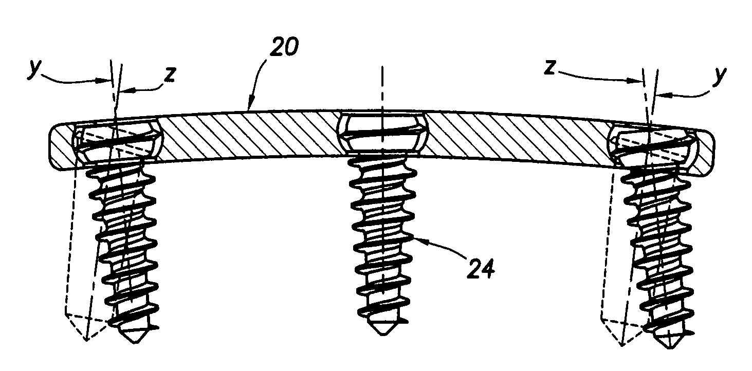
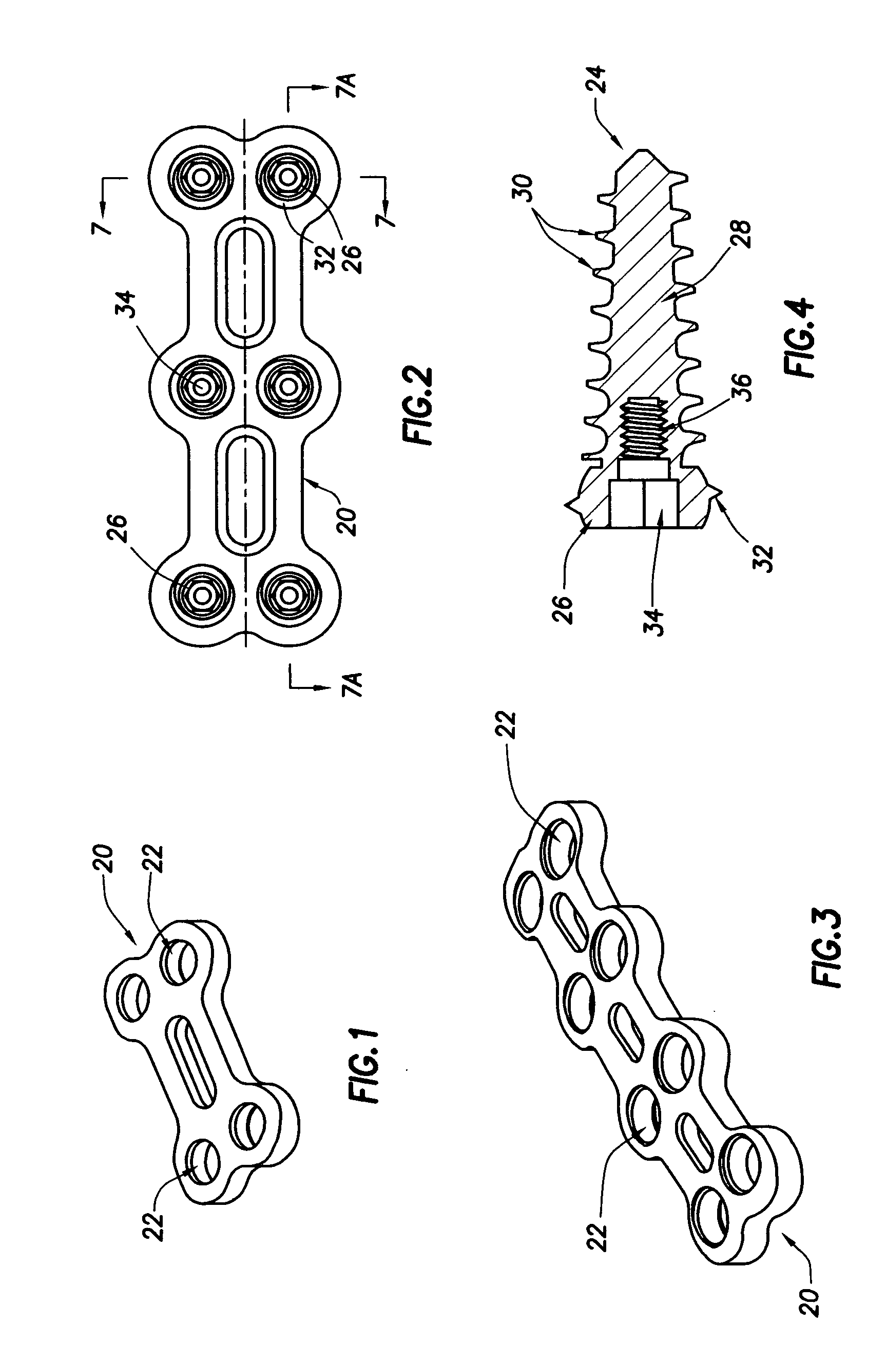
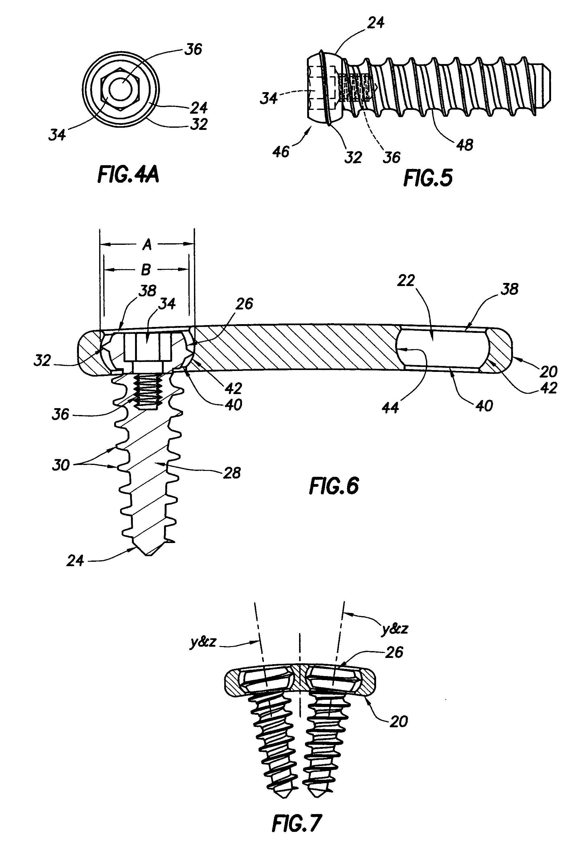
[0023]Referring now to FIGS. 1-3, a preferred embodiment of a plate comprising one component of a multi-axis connection for a spinal stabilizer constructed in accordance with the present invention is shown. The preferred embodiment of this plate, indicated generally at reference numeral 20, is provided with a plurality of holes 22 spaced along the length of the plate at locations corresponding to the spacing of the vertebrae of the spinal column of a patient (not shown) for receiving screws as shown in FIG. 2 at reference numeral 24 for screwing into the body of the respective vertebra to affix the stabilizer to the spine. The three plates 20 shown in FIGS. 1, 2, and 3 are sized, and define a corresponding number of holes 22, for stabilizing two, three, and four vertebrae, respectively. Although not shown very well in FIGS. 1-3, plate 20 is curved along its cross-sectional axis (see FIGS. 7, 7B, and 7C) and arched, or curved, along its longitudinal axis (see FIGS. 6 and 7A) so as to...


PUM


Abstract

A multi-axis connection for transferring load from the vertebrae of a patient to a plate extending from one vertebra to another vertebra when the plate is affixed to the respective vertebrae by screwing screws into the bodies of the vertebrae. The screws extend through holes in the plate at the level of the respective vertebrae, each screw being oriented at any one of a plurality of angles relative to the plate so as to effectively transfer load. The threaded shank of each screw is screwed into the vertebral body and the head of each screw is positioned in the central portion of the hole, the hole being defined by an aperture, an opening through which the shank of the screw extends, and the central portion between the aperture and the opening. The diameter of the head of the screw is larger than the diameter of the aperture of the hole in the plate and the head is provided with a screw thread that engages the smaller diameter aperture of the hole to pull the head of the screw into the central portion of the hole when the screw is rotated relative to the plate, the head of the screw being retained within the hole by the smaller diameter aperture and the opening of the hole.

Description

BACKGROUND OF THE INVENTION[0001]The present invention relates to multi-axis apparatus and methods for internal spinal fixation. In more detail, the present invention relates to a connection for an internal spinal fixation system, and a method of stabilizing, or fixing, the spine, utilizing multiple axes for transferring load from the patient's spinal column to the stabilizer.[0002]Treatment of a damaged or diseased intervertebral disk continues to be a challenging field of medicine. The classical treatment for a damaged or diseased disk is removal of all or a portion of the disk from between the vertebrae. However, removing the disk increases the instability of the spine. If only a portion of the disk is removed, the intervertebral disk space is commonly filled with a bone plug or prosthetic device and the space around the plug or the implant is packed with bone chips to promote fusion of the adjacent disks, thereby increasing spinal stability. However, depending upon the particula...

Claims


Application Information

Patent Timeline
Patent Type & Authority Applications(United States)
IPC IPC(8): A61B17/70A61B17/08A61B17/56A61B17/58A61B17/04
CPCA61B17/7059A61B17/8057A61B17/8052
Inventor PISHARODI, MADHAVAN
Owner PERUMALA HLDG LLC A BELIZE LLC
Why Eureka
Try Eureka