Hot-Strip Cooling Device and Cooling Method

a cooling device and hot-rolled steel technology, which is applied in the direction of heat treatment equipment, furnaces, manufacturing tools, etc., can solve the problems of reducing the purging reducing the purging effect in more downstream regions, and unable to obtain the purging effect of constraining rolls (purging rolls). the effect of reducing the margin of steel strips to be cut off and stable quality of steel strips

Active Publication Date: 2009-01-22
JFE STEEL CORP
View PDF4 Cites 10 Cited by
  • Summary
  • Abstract
  • Description
  • Claims
  • Application Information

AI Technical Summary

Benefits of technology

[0032]According to the present invention, cooling can be performed uniformly from the leading end to the trailing end of a steel strip, whereby the quality of the steel strip can be stabilized. Consequently, the margin of the steel strip to be cut off is reduced. Thus the yield becomes high.

Problems solved by technology

In the method disclosed in Patent Document 1, however, the amount of residual coolant on the steel strip becomes larger in more downstream regions.
This reduces the purging effect in more downstream regions.
This means that the purging effect that would be produced by the constraining rolls (purging rolls) cannot be obtained.

Method used


Image

  • Hot-Strip Cooling Device and Cooling Method
  • Hot-Strip Cooling Device and Cooling Method
  • Hot-Strip Cooling Device and Cooling Method

Examples


example 1

Present Example 1

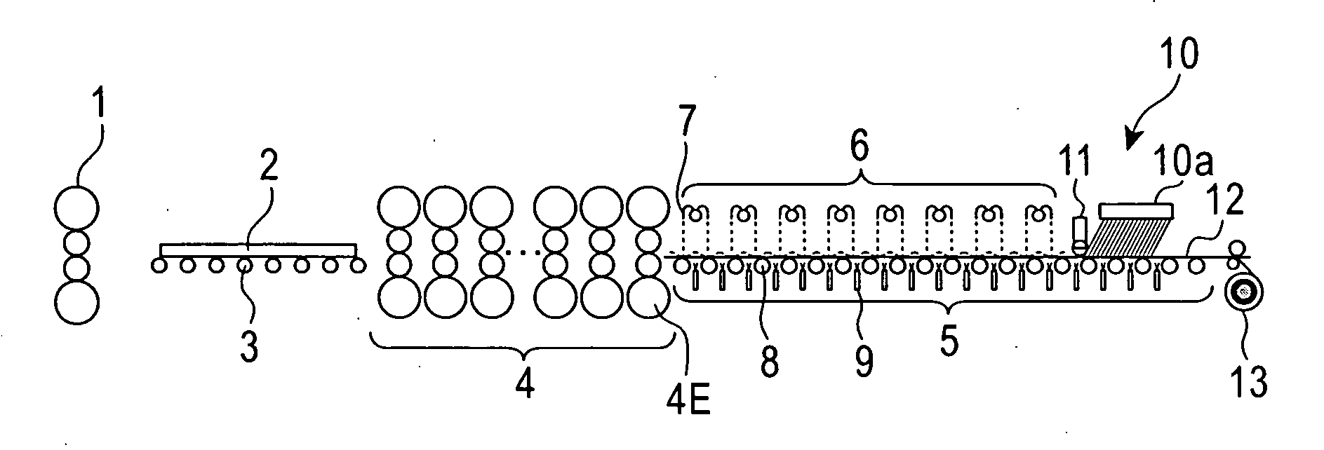
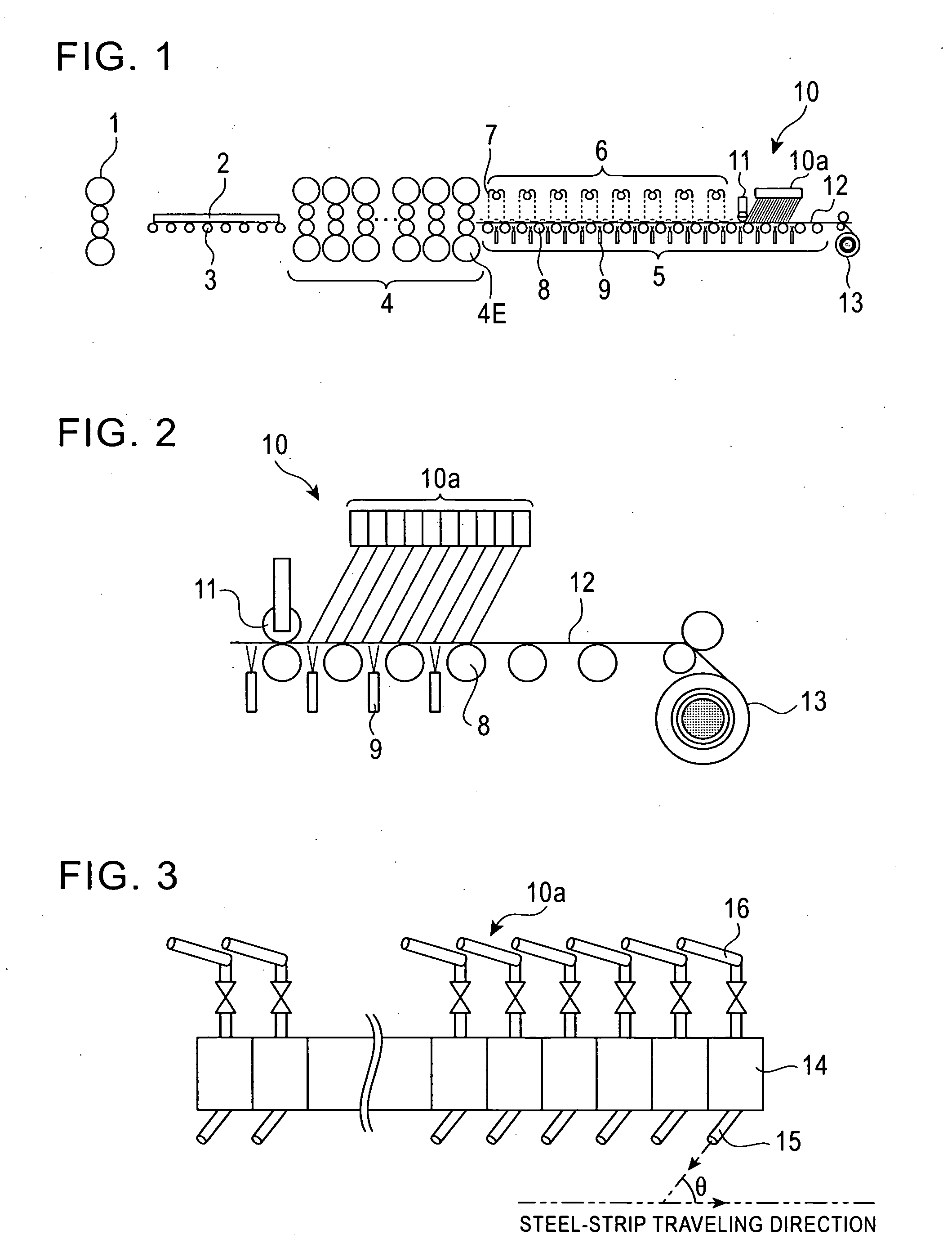
[0102]The present invention was implemented on the basis of the first embodiment, which is denoted as Present Example 1. Specifically, a system configured as shown in FIG. 1 was used. In the cooling-device body 10a, on-off control of rod-like flows was possible for each unit including one row of the round nozzles, as shown in FIG. 3. Further, as shown in FIG. 8B, with respect to the widthwise arrangement positions in an upstream row, the widthwise arrangement positions in an adjacent downstream row were shifted by ½ of the widthwise nozzle-arrangement pitch. Further, as shown in FIG. 2, the pinch roll 11 was disposed on the upstream side with respect to the cooling-device body 10a.

[0103]The finished thickness of the steel strip was set to 2.8 mm. The steel-strip speed at the exit of the finishing stand 4 was 700 mpm at the leading end, and was gradually increased to a maximum speed of 1000 mpm (16.7 m / s) after the leading end of the steel strip reached the down coi...

example 2

Present Example 2

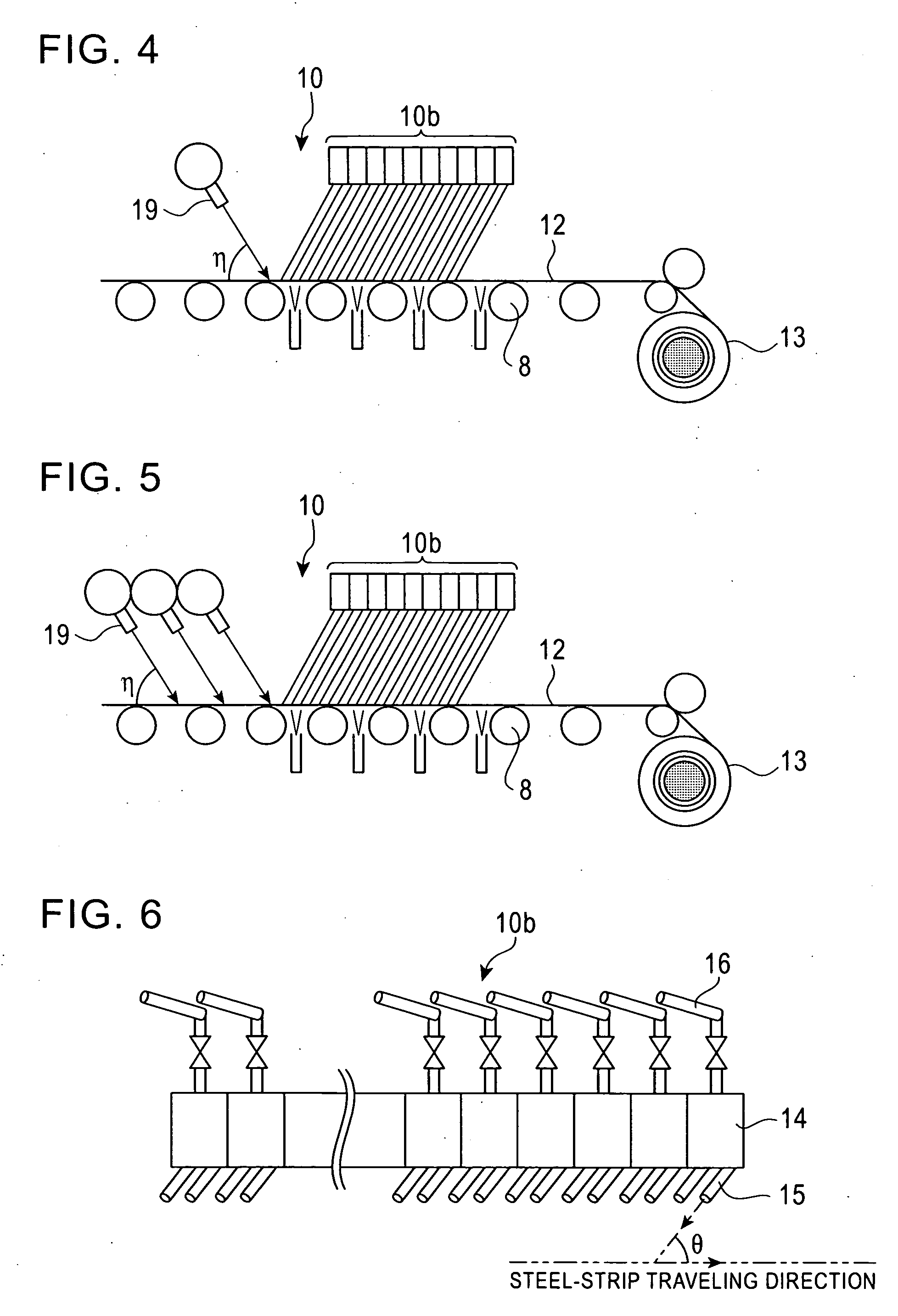
[0108]The present invention was implemented on the basis of the second embodiment, which is denoted as Present Example 2. Specifically, as described above, a system having a configuration almost the same as the one shown in FIG. 1 was used. In the cooling-device body 10b, on-off control of rod-like flows was possible for each unit including two rows of the round nozzles, as shown in FIG. 6. Further, as shown in FIG. 8B, with respect to the widthwise arrangement positions in an upstream row, the widthwise arrangement positions in an adjacent downstream row were shifted by ½ of the widthwise nozzle-arrangement pitch. Further, as shown in FIG. 5, a plurality of rows of the rod-like-flow ejection nozzles 19 that eject purging fluid were disposed on the upstream side with respect to the cooling-device body 10b.

[0109]The finished thickness of the steel strip was set to 2.8 mm. The steel-strip speed at the exit of the finishing stand 4 was 700 mpm at the leading end, and ...


PUM

PropertyMeasurementUnit
angleaaaaaaaaaa
lengthaaaaaaaaaa
diameteraaaaaaaaaa

Abstract

A hot-strip cooling device and a cooling method are provided wherein uniform cooling of a hot-rolled steel strip using coolant is possible from the leading end to the trailing end of the steel strip. A cooling device (10) includes a plurality of round nozzles (15) disposed obliquely in such a manner as to eject rod-like flows of coolant at an ejection angle θ toward the upstream side in a direction in which a steel strip (12) travels, and a pinch roll (11) disposed on the upstream side with respect to the round nozzles (15) and configured to pinch the steel strip (12) in combination with a roller table (8).

Description

TECHNICAL FIELD[0001]The present invention relates to cooling devices and cooling methods for cooling hot-rolled steel strips.BACKGROUND ART[0002]In general, hot strips are manufactured in the following manner: A slab is heated to a predetermined temperature in a heating furnace. The heated slab is rolled by using a roughing stand, whereby a rough bar having a predetermined thickness is obtained. The rough bar is rolled by using a continuous finishing stand constituted by a plurality of rolling stands, whereby a steel strip having a predetermined thickness is obtained. The steel strip is cooled by using a cooling device provided above a run-out table and subsequently is coiled by using a down coiler.[0003]In this process, in the cooling device provided above the run-out table for continuously cooling the hot steel strip that has been subjected to hot rolling, a plurality of linear laminar flows of coolant are ejected from round-type laminar-flow nozzles onto roller-tables for convey...

Claims


Application Information

Patent Timeline
Patent Type & Authority Applications(United States)
IPC IPC(8): B21B27/06
CPCB21B45/0218B21B45/0281B21B45/0233B21B45/02B21B45/06
Inventor UEOKA, SATOSHIFUJIBAYASHI, AKIONAKATA, NOAKIKUROKI, TAKASHITOMITA, SHOUGO
Owner JFE STEEL CORP
Why Eureka
Try Eureka