Hollow valve for internal combustion engine, and internal combustion engine having the hollow valve

a technology for internal combustion engines and hollow valves, which is applied in the direction of valve arrangements, lift valves, engine cooling apparatus, etc., can solve the problems of medium not being able to contact a wall, medium not necessarily cooled, so as to reduce or prevent the temperature rise of intake air, improve the cooling effect, and improve the cooling

Inactive Publication Date: 2009-01-22
TOYOTA JIDOSHA KK +2
View PDF2 Cites 16 Cited by
  • Summary
  • Abstract
  • Description
  • Claims
  • Application Information

AI Technical Summary

Benefits of technology

[0021]With the above arrangement, the heat of the wall portion is transferred to a portion of the umbrella portion that is close to the valve seat, as well as the heat-conduction medium (the coolant or stem portion). Accordingly, when it is not desired to raise the temperature of the stem portion, which would result in an increase in the temperature of intake air, the high-thermal-conductivity member are placed in position so that a relatively large amount of heat is dissipated to the portion close to the valve seat, thereby to suppress or prevent a temperature rise of the intake air.
[0022]In the hollow valve for the internal combustion engine according to the invention, the high-thermal-conductivity members have a high capability of dissipating heat, and heat is transferred from the high-thermal-conductivity members to the heat-conduction medium, so that the umbrella portion, in particular, can be favorably cooled.

Problems solved by technology

Therefore, the heat transfer medium (coolant) does not necessarily contact uniformly with the respective walls of the umbrella portion and stem portion in the cavity, and the umbrella portion and the stem portion may not be cooled uniformly.
Namely, in the hollow engine valve of the related art, even if heat is transferred to the heat transfer medium in a certain portion of the umbrella portion in the cavity, so that the heat can be dissipated to an object, such as a stem portion, to which heat is to be transferred, the heat transfer medium may not be able to contact a wall of the cavity in another portion of the umbrella portion, and thus cannot take heat from this portion.

Method used


Image

  • Hollow valve for internal combustion engine, and internal combustion engine having the hollow valve
  • Hollow valve for internal combustion engine, and internal combustion engine having the hollow valve
  • Hollow valve for internal combustion engine, and internal combustion engine having the hollow valve

Examples


first embodiment

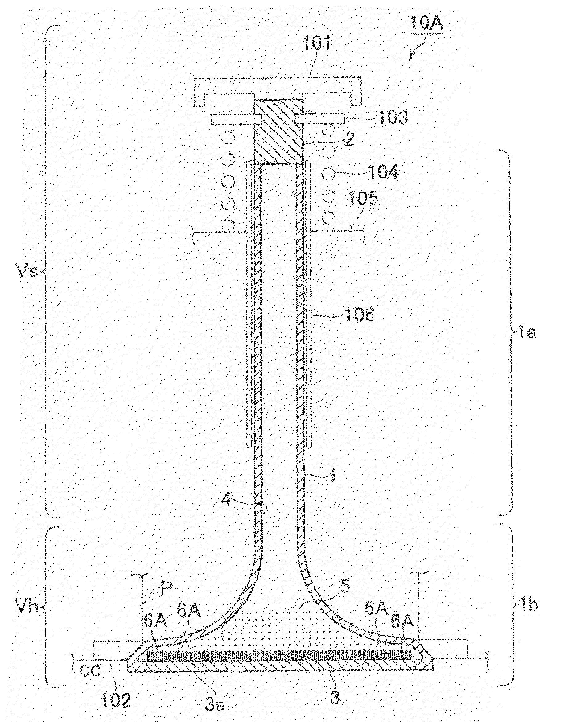
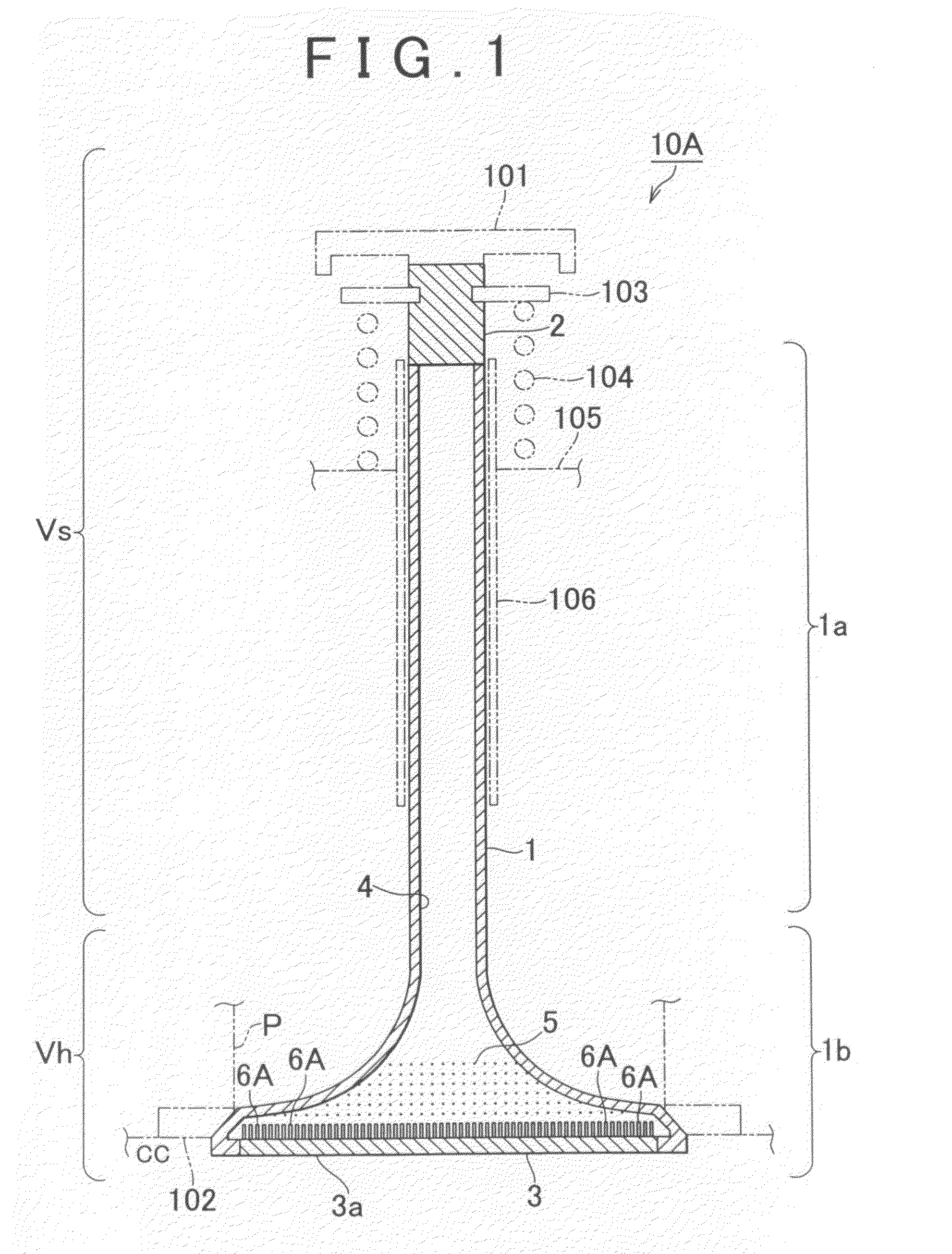
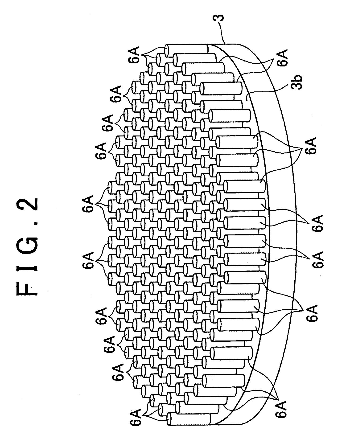
[0037]A hollow valve for an internal combustion engine according to the invention will be described with reference to FIG. 1 and FIG. 2.

[0038]In FIG. 1, reference numeral 10A denotes the hollow engine valve of the first embodiment. The hollow engine valve 10A of the first embodiment may be used in an intake or exhaust valve actuating mechanism (a mechanism including, for example, a valve lifter 101) of the internal combustion engine, which is not illustrated in the drawings. In operation, the hollow engine valve 10A reciprocates in the axial direction so as to communicate a combustion chamber CC of the engine and an intake port P (or the combustion chamber CC and an exhaust port P) with each other or interrupt communication between the combustion chamber CC and the intake or exhaust port P.

[0039]The hollow engine valve 10A of the first embodiment is divided roughly into a stem portion (so-called valve stem) Vs and an umbrella portion Vh provided at one end of the stem portion Vs. Th...


PUM


Abstract

In a hollow valve for an internal combustion engine, including a stem portion, an umbrella portion provided at one end of the stem portion, a gastight cavity that communicates the interior of the stem portion with that of the umbrella portion, and a coolant contained in the cavity, the umbrella portion has a wall portion (a lower cap) having a combustion-chamber-side wall that forms a part of a wall of a combustion chamber of the engine, and a cavity-side wall that forms a part of a wall of the cavity, and at least one high-thermal-conductivity member is provided on the cavity-side wall, for conduction of heat between the wall portion and one of at least the coolant and the stem portion as a heat-conduction medium.

Description

INCORPORATION BY REFERENCE[0001]The disclosure of Japanese Patent Application No. 2007-178867 filed on Jul. 6, 2007, including the specification, drawings and abstract, is incorporated herein by reference in its entirety.BACKGROUND OF THE INVENTION[0002]1. Field of the Invention[0003]This invention relates to a hollow valve for an internal combustion engine for use in an intake / exhaust valve actuating mechanism of the internal combustion engine, and also relates to an internal combustion engine in which the hollow valve or valves is / are mounted.[0004]2. Description of the Related Art[0005]In an intake / exhaust valve actuating mechanism of an internal combustion engine, a valve is provided for permitting or interrupting communication between an intake port and the combustion chamber or between an exhaust port and the combustion chamber. Generally, the valve is roughly divided into an umbrella portion and a stem portion, and the stem portion is adapted to reciprocate in its axial direc...

Claims


Application Information

Patent Timeline
Patent Type & Authority Applications(United States)
IPC IPC(8): F01P1/08
CPCF01L3/14
Inventor SUZUKI, TAKAOKAWAI, KIYOYUKIISHIDA, MASAOAOYAGI, KENICHIDESAKI, TORU
Owner TOYOTA JIDOSHA KK
Why Eureka
Try Eureka