
Rotationally indexable cutting elements and drill bits therefor

a cutting element and indexing technology, applied in cutting machines, earth drilling and mining, construction, etc., can solve the problems of reducing the effectiveness of drilling and cutting the subterranean formation, reducing the life of drill bits, and erode the surface of pdc cutters, so as to increase the utilization of the diamond table cutting surface

Active Publication Date: 2009-01-22
BAKER HUGHES INC
View PDF15 Cites 100 Cited by
  • Summary
  • Abstract
  • Description
  • Claims
  • Application Information

AI Technical Summary

Benefits of technology

[0005]In one embodiment, a cutting element for use with a drill bit is provided which provides for in-field replacement upon a drill bit. The cutting element may further enable increased utilization of its diamond table cutting surface without replacement or repair thereof.

Problems solved by technology

However, increased rotational speed also has tended to decrease the life of the drill bit due to increased wear and damage of cutting elements mounted on the bit.
While the drilling fluid extends the life of the PDC cutters, the entrained particulates in the high flow rate drilling fluid comprised of solids in the fluid as well as formation cuttings may erode surfaces of the PDC cutters.
Wear of surfaces on the PDC cutters may also be attributable to sliding contact of the PDC cutters with the formation being drilled under weight on bit, as well as by impact stresses caused by a phenomenon known as bit “whirl.” When the PDC cutters wear beyond a point where a large wear flat develops and the exposure of the PDC cutter above the surrounding bit face substantially reduces the depth of cut into the adjacent formation, their effectiveness in penetrating and cutting the subterranean formation is diminished, thus requiring repair and / or replacement of the PDC cutters.
In order to appropriately replace and repair the worn or damaged PDC cutters that are brazed into the pockets of the bit body, the drill bit is often (if not always) returned to a repair facility qualified to repair the drill bit, resulting in lost utilization of the drill bit in terms both of time and revenue from drilling.
The repair and / or replacement of PDC cutters is further complicated by the manufacturing process of brazing the PDC cutters into the pockets, which requires the controlled application of heat to de-braze and remove any worn and damaged PDC cutters without affecting other cutters on the bit, particularly those not needing repair, followed by brazing in replacement PDC cutters.

Method used


Image

  • Rotationally indexable cutting elements and drill bits therefor
  • Rotationally indexable cutting elements and drill bits therefor
  • Rotationally indexable cutting elements and drill bits therefor

Examples


Embodiment Construction

[0019]In the description which follows, like elements and features among the various drawing figures are identified for convenience with the same or similar reference numerals.

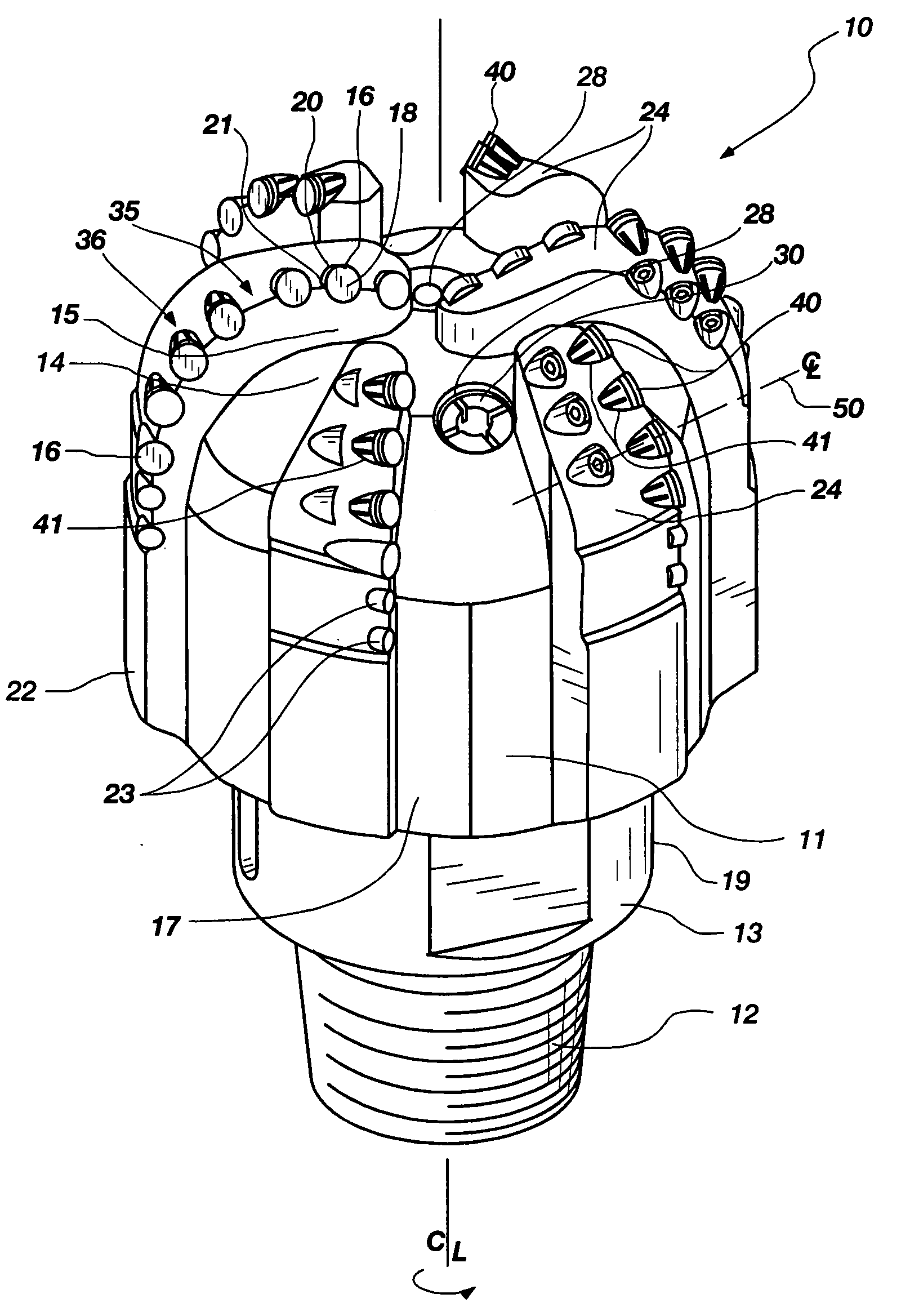
[0020]FIG. 1 shows a perspective view of a drill bit 10 in accordance with an embodiment of the invention. The drill bit 10 is configured as a fixed cutter rotary full bore drill bit, also known in the art as a “drag” bit. The drill bit 10 includes a bit crown or body 11 comprising, for example, tungsten carbide infiltrated with a metal alloy binder, steel, or sintered tungsten or other suitable carbide, nitride or boride as discussed in further detail below, and coupled to a support 19. The support 19 includes a shank 13 and a crossover component (not shown) coupled to the shank 13 in this embodiment of the invention It is recognized that the support 19 may be made from a unitary material piece or multiple pieces of material in a configuration differing from the shank 13 being coupled to the crossover by weld...


PUM


Abstract

A cutting element for use with a drill bit includes a substrate having a longitudinal axis, a lateral surface substantially symmetric about the longitudinal axis and one or more key elements coupled to the lateral surface. The lateral surface lies between an insertion end and a cutting end of the substrate. The one or more key elements are substantially axially aligned with the longitudinal axis and configured to selectively rotationally locate the substrate in a pocket. A drill bit configured for retaining a cutting element having one or more key elements is also disclosed.

Description

FIELD OF INVENTION[0001]The invention, in various embodiments, relates to drill bits for subterranean drilling and, more particularly, to rotationally indexable cutting elements as well as drill bits configured for mounting rotationally indexable cutting elements thereon.BACKGROUND OF INVENTION[0002]Conventional rotary drill bits, such as fixed cutter rotary drill bits for subterranean earth boring, have been employed for decades. It has been found that increasing the rotational speed of such drill bit attached to a drill string has, for a given weight on bit, increased the rate of penetration into the subterranean earth. However, increased rotational speed also has tended to decrease the life of the drill bit due to increased wear and damage of cutting elements mounted on the bit. The cutting elements most commonly employed are referred to as polycrystalline diamond compact (PDC) cutters, which comprise a diamond table formed on a supporting substrate of cemented carbide such as tu...

Claims


Application Information

Patent Timeline
Patent Type & Authority Applications(United States)
IPC IPC(8): E21B10/46
CPCE21B10/633E21B10/43
Inventor SHERWOOD, JR., WILLIAM H.
Owner BAKER HUGHES INC
Features
  • Generate Ideas
  • Intellectual Property
  • Life Sciences
  • Materials
  • Tech Scout
  • Unparalleled Data Quality
  • Higher Quality Content
  • 60% Fewer Hallucinations
Learn More