Rotary atomizing-head type coating machine

a coating machine and atomizer technology, applied in coatings, combustion types, lighting and heating apparatuses, etc., can solve the problems of accelerating the degradation of electrical insulation properties of housing surfaces, inability to electrostatically apply coating operation, and moisture condensation or sweating very likely to occur on housing surfaces, so as to prevent moisture condensation and easy formation

Active Publication Date: 2009-01-22
ABB (SCHWEIZ) AG
View PDF12 Cites 13 Cited by
  • Summary
  • Abstract
  • Description
  • Claims
  • Application Information

AI Technical Summary

Benefits of technology

[0029]In this case, since the housing is composed of the main housing body and the cover, the circumventive space can be easily formed at

Problems solved by technology

Therefore, if the housing is cooled by cold exhaust air, moisture condensation or sweating is very likely to occur on housing surfaces in a coating booth of high temperature and humidity.
The moisture condensation on housing surfaces gives rise to a problem that a high voltage to be applied to a paint is leaked to the earth ground, making an electrostatic coating operation infeasible.
Further, if the housing is elec

Method used


Image

  • Rotary atomizing-head type coating machine
  • Rotary atomizing-head type coating machine
  • Rotary atomizing-head type coating machine

Examples


first embodiment

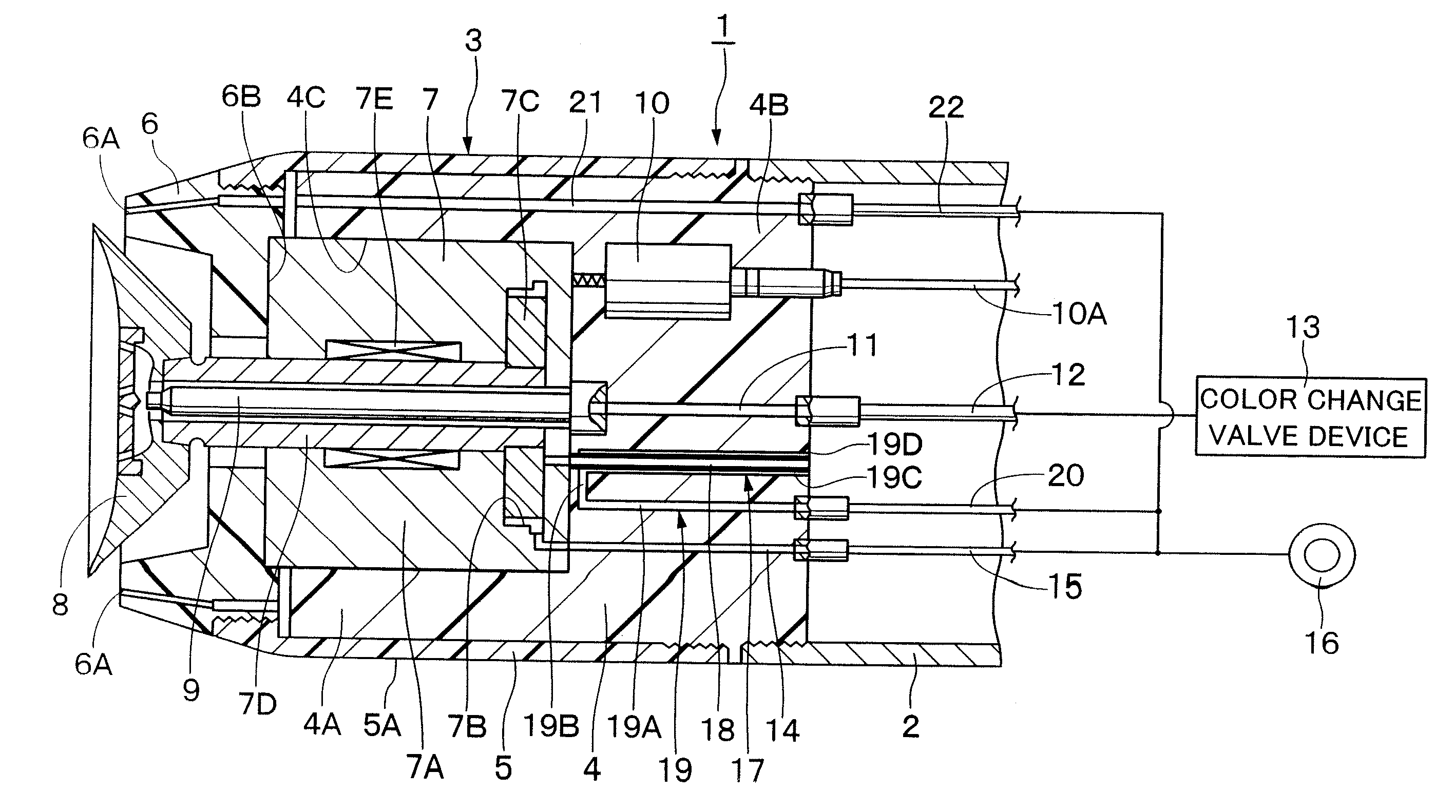
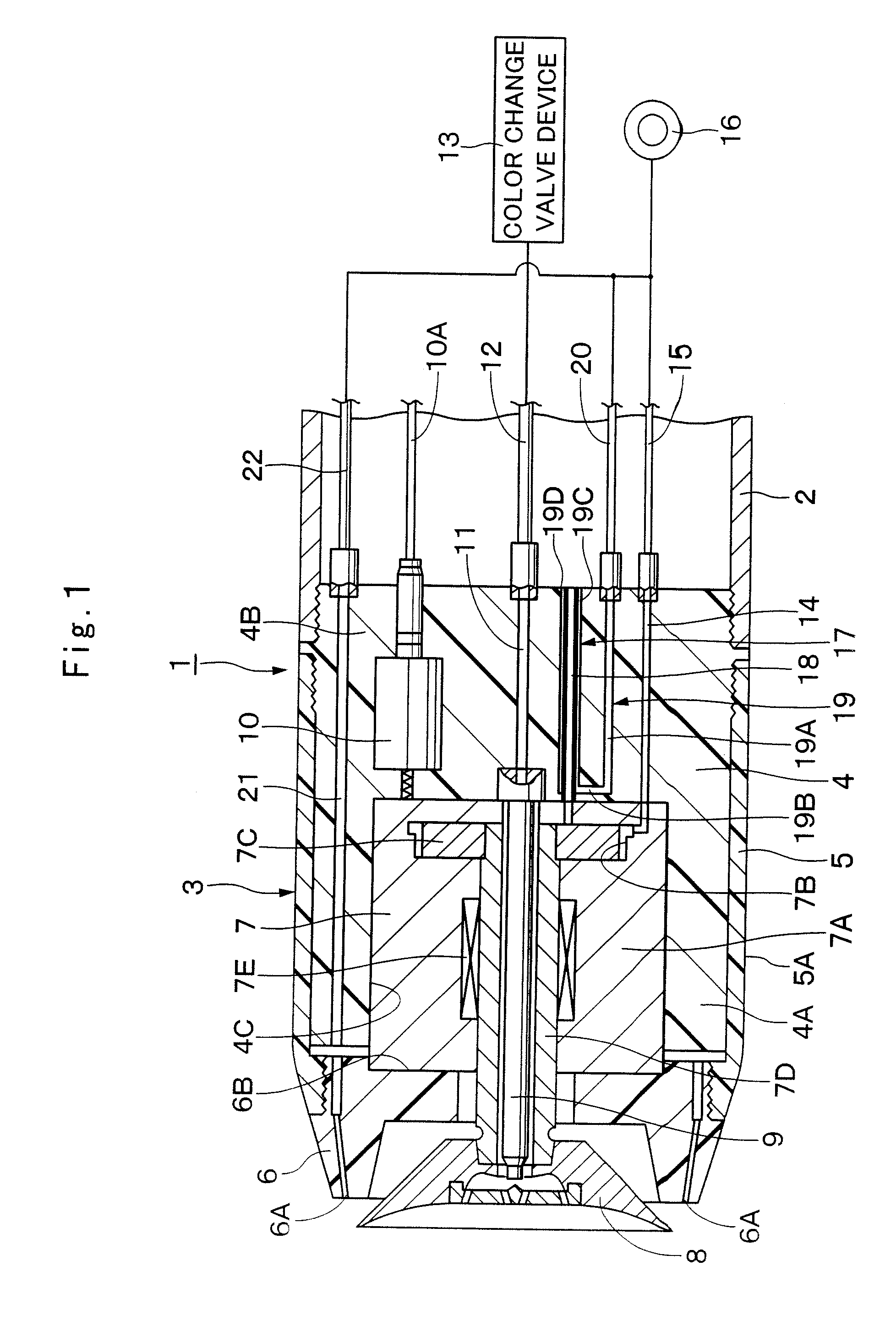
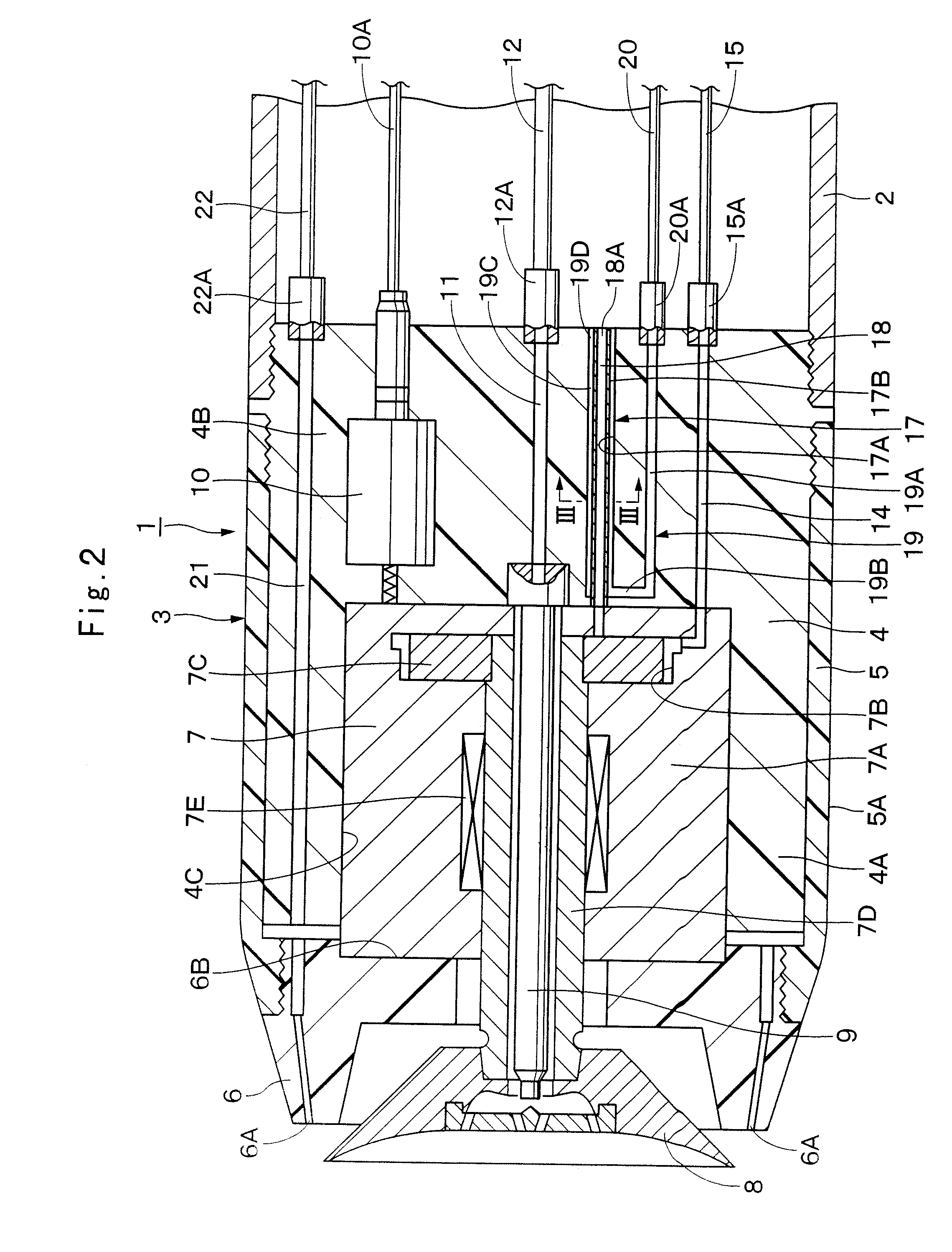
[0074]Being arranged in the manner as described above, the rotary atomizing head type coating machine 1 of the first embodiment can be used for a coating operation in the following manner.

[0075]In the first place, high pressure turbine air is introduced into the turbine chamber 7B of the air motor 7 through the air pipe 15 and turbine air passage 14 to rotationally drive the turbine 7C with turbine air. By so doing, the rotary atomizing head 8 is put in high speed rotation along with the rotational shaft 7D. In this state, paint of a selected color is supplied from the color changing valve device 13 to the rotary atomizing head 8 through the paint pipe 12, paint passage 11 and feed tube 9, and finely atomized paint particles are sprayed from the rotary atomizing head 8.

[0076]At this time, paint (paint particles) is charged with a high voltage by the high voltage generator 10. Therefore, charged paint particles are urged to fly toward a work which is connected to the earth ground, an...

second embodiment

[0090]Indicated at 36 is a heat insulating air passage which is provided in and through the bottom section 4B of the main housing body 4 in the This heat insulating air passage 36 is composed of a heat insulating air supply passage section 36A, a heat insulating air intercommunicating passage section 36B, a heat insulating air discharging passage section 36C and a heat insulating air discharging end opening 36D, which are arranged substantially in U-shape as a whole, and communicated with the outside through the bottom section 4B.

[0091]In this instance, the heat insulating air supply passage section 36A on the upstream side of the heat insulating air passage 36 is an annular passage which is formed as an outer passage between the outer passage bore 31A and inner conduit pipe 31B of the first dual passage 31. Further, the heat insulating air supply passage section 36A is formed throughout the bottom section 4B of the main housing body 4, the heat insulating air supply passage sectio...

third embodiment

[0099]Designated at 46 is a heat insulating air passage of the third embodiment, which is provided in the bottom section 4B of the main housing body 4. This heat insulating air passage 46 is composed of a heat insulating air supply passage section 46A, a heat insulating air intercommunicating passage section 46B, a heat insulating air discharging passage section 46C and an discharging end opening 46D, which are arranged substantially in U-shape, and communicated with the outside through the bottom section 4B.

[0100]In this instance, the heat insulating air supply passage section 46A in the upstream side of the heat insulating air passage 46 is an annular passage which is formed between the outer passage bore 41A and the inner conduit pipe 41B of the first dual passage 41. Further, the heat insulating air supply passage section 46A is extended in an axial direction along and around the first exhaust air passage 44. Furthermore, the heat insulating air supply passage section 46A is for...


PUM


Abstract

A rotary atomizing-head type coating machine, wherein a paint passage for flowing a paint to a rotary atomizing-head, a turbine air passage flowing a turbine air to the turbine of an air motor, a discharge air passage for flowing the turbine air after driving the turbine to the outside in the form of a discharge air, and a heat insulating air discharge passage of a heat insulated air passage axially extending while surrounding the discharge air passage and allowing hot heat insulated air to flow therein are formed in the bottom part of a housing body forming a housing. Thus, even if the turbine air expanded in a heat insulated state and reduced in temperature flows in the discharge air passage, the housing can be prevented from being cooled by the discharge air by flowing a heat insulated air with a temperature higher than that of the discharge air in the heat insulated air discharge passage.

Description

TECHNICAL FIELD[0001]This invention relates to a rotary atomizing head type coating machine suitable for use in coating vehicle bodies, furniture, electric appliances and the like.BACKGROUND ART[0002]Because of high paint deposition efficiency and satisfactory finish quality, rotary atomizing head type coating machines have been widely used for coating vehicle bodies, furniture, electric appliances and the like. A rotary atomizing head type coating machine is composed of a tubular housing for accommodating a motor, an air motor accommodated within a motor compartment of the housing to drive a rotational shaft by a turbine, a bell- or cup-shaped rotary atomizing head mounted on a fore end portion of the rotational shaft of the air motor at a position on the front side of the housing, and a paint passage for paint supply to the rotary atomizing head (e.g., as disclosed in Japanese Patent Laid-Open No. S60-14959 and H8-1046).[0003]The housing of the rotary atomizing head type coating m...

Claims


Application Information

Patent Timeline
IPC IPC(8): B05B5/04B05B3/02B05B7/16B05B3/04
CPCB05B3/1064B05B5/001B05B5/04B05B13/0431B05B5/0415B05B5/0426B05B5/0407B05B3/001
Inventor YASUDA, SHINICHI
Owner ABB (SCHWEIZ) AG
Why Eureka
Try Eureka