
Motor driven valve and cooling/heating system

Inactive Publication Date: 2009-01-22
FUJIKOKI CORP
View PDF8 Cites 31 Cited by
  • Summary
  • Abstract
  • Description
  • Claims
  • Application Information

AI Technical Summary

Benefits of technology

[0015]With the motor-driven valve according to the present invention, since flow rate of fluid can be controlled in the first valve opening range, and a large amount of fluid can be flown in the second valve opening range, it is possible, for instance, to use the motor-driven valve for cooling / heating systems and to control flow rate of a refrigerant in cooling in the first valve opening range and allow a large amount of the refrigerant to pass the valve in heating. With this, it is avoidable to separately connect a check valve in parallel to a pipe as well as a problem caused by using a valve with a built-in check valve, which increases cost and size due to intricate construction of the valve itself, can be eliminated, because only one valve can satisfy the performance of the conventional valve, resulting in decreased cost and size.
[0026]As described above, with the present invention, it becomes unnecessary to separately connect a check valve to a pipe in parallel and to prepare a built-in check valve structure, and the performance of the conventional valve can be satisfied with a single valve with reduced cost and downsizing.

Problems solved by technology

In the conventional cooling / heating system shown in FIG. 5, although a thermal expansion valve with a built-in check valve or a thermal expansion valve and a check that are connected through a pipe in parallel are used, the check valve portion is large in diameter in comparison to the diameter of an opening of the expansion valve to reduce pressure loss, so that the construction of the thermal expansion valve with a built-in check valve itself becomes intricate and the size of the valve becomes large, resulting in increased manufacturing cost of the valve.
On the other hand, the construction in which a thermal expansion valve and a check valve are connected in parallel requires additional piping and boding works, resulting in increased area to mount the valves and increased cost.
And, in order to improve save-energy efficiency, an electronic expansion valve is used in place of the thermal expansion valve, which causes almost the same problem as described above.

Method used


Image

  • Motor driven valve and cooling/heating system
  • Motor driven valve and cooling/heating system
  • Motor driven valve and cooling/heating system

Examples


Embodiment Construction

[0034]Next, embodiments of the present invention will be explained with reference to drawings.

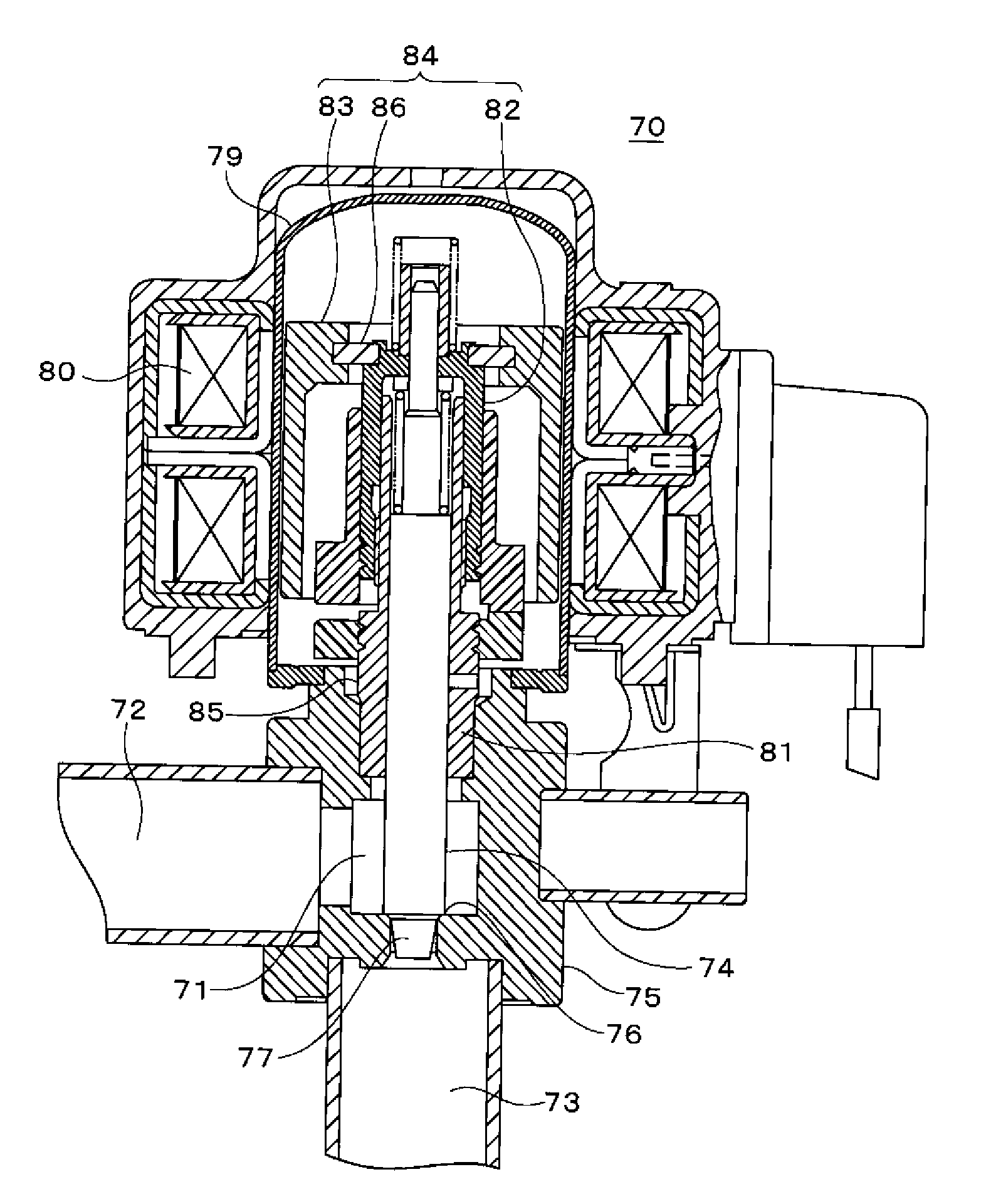
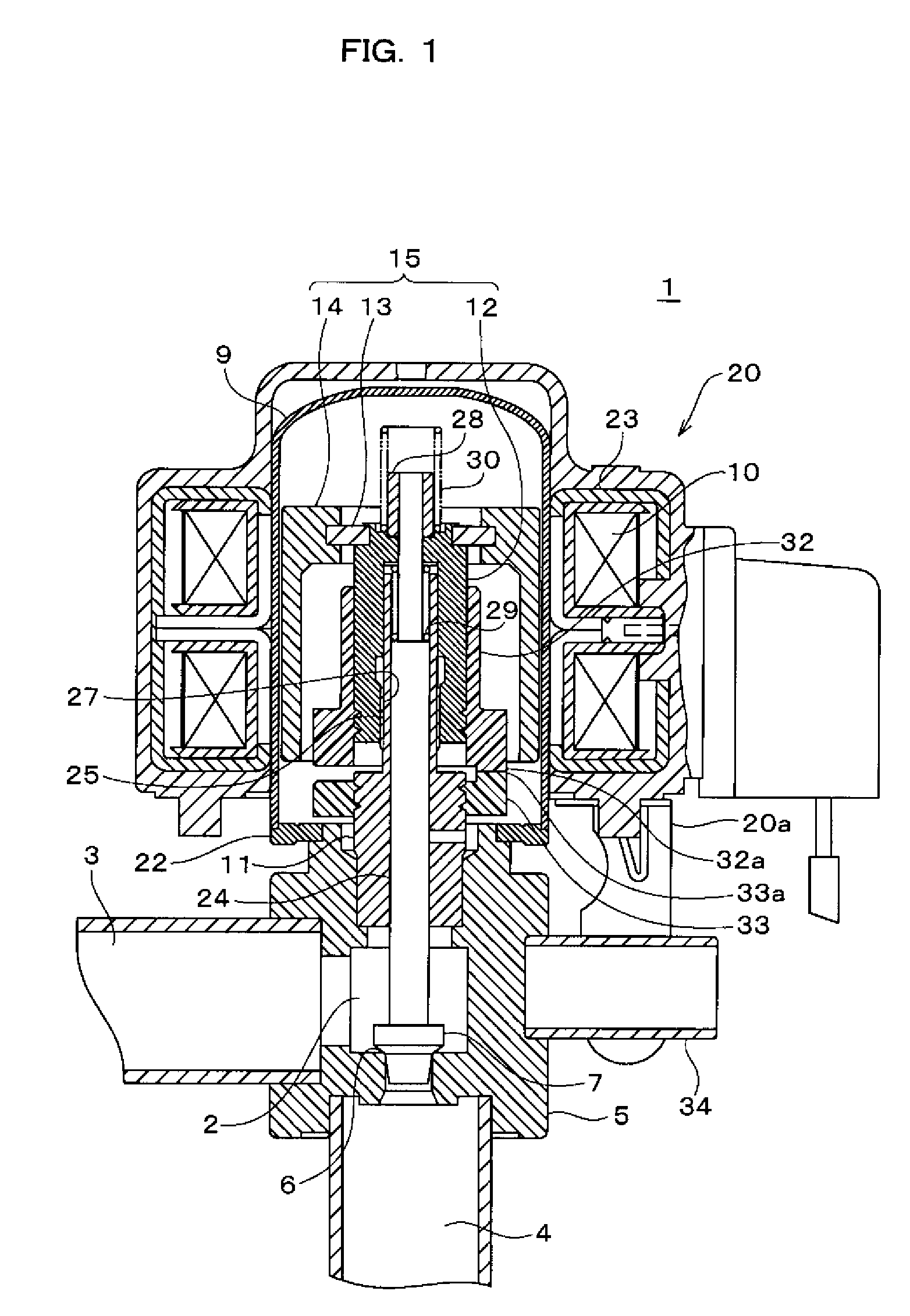
[0035]FIG. 1 shows a motor-driven valve according to an embodiment of the present invention. The motor-driven valve 1 roughly comprises: a valve main body 5 having a first flow passage 3 and a second flow passage 4 that communicate with a valve chamber 2; a valve body 7 that contacts with and is separated from a valve seat 6 of the valve main body 5; a cylindrical shield case 9; a stator coil (driving coil) 10 disposed outside of the sealed case 9; a rotor 15 that rotates in the sealed case 9 through magnetization by feeding current to the stator coil 10 so as to be movable in a valve opening / closing directions and is provided with a permanent magnet 14 fixed to a cylindrical valve shaft holder 12 through a stop ring 13 and the like; a male screw pipe 11 and the valve shaft holder 12 that allow the valve body 7 to contact with and be separated from the valve seat 6 through screw-feeding act...


PUM


Abstract

To provide a motor-driven valve without requirement that a check valve is separately connected through piping in parallel and without a built-in check valve. A motor-driven valve 1 according to the present invention having a valve body 7 linearly moving by rotation of a rotor 15 of an electric motor and controlling a valve opening between the valve body 7 and a valve seat 6, and the motor-driven valve 1 is characterized in that: in a first valve opening range, the valve opening and flow rate of fluid have a predetermined correlation, and in a second valve opening range, flow rate more or equal to four time as much as controllable maximum flow rate in the first valve opening range can pass the valve 1. It is possible to use the motor-driven valve 1 for cooling / heating systems and to control flow rate of refrigerant in cooling in the first valve opening range and allow a large amount of the refrigerant to pass the valve in heating, so that only one electronic valve can satisfy performance of conventional valves.

Description

CROSS-REFERENCE TO RELATED APPLICATIONS[0001]The present application claims priority to Japanese Patent Application No. 2007-174783 entitled MOTOR-DRIVEN VALVE AND COOLING / HEATING SYSTEM filed on Jul. 3, 2007.STATEMENT RE: FEDERALLY SPONSORED RESEARCH / DEVELOPMENT[0002]Not Applicable.BACKGROUND[0003]1. Field of the Invention[0004]The present invention relates to a motor-driven valve that can be used as an electronic expansion valve with check valve function in cooling / heating systems and a cooling / heating system with the motor-driven valve.[0005]2. Description of the Related Art[0006]As a conventional cooling / heating system (heat pump cycle), a system shown in FIG. is used. The cooling / heating system 51 is composed of a compressor 52; a switching valve 53 for switching flow passages for refrigerant to switch cooling / heating operation; an outdoor heat exchanger 54; a distributor 55 and a thermal expansion valve 56 through which the refrigerant passes in heating; a check valve 57 throu...

Claims


Application Information

Patent Timeline
IPC IPC(8): F16K31/04
CPCF16K31/047F25B41/04F25B13/00
Inventor HOKAZONO, HIDEKIHARADA, TAKAO
Owner FUJIKOKI CORP
Features
  • Generate Ideas
  • Intellectual Property
  • Life Sciences
  • Materials
  • Tech Scout
  • Unparalleled Data Quality
  • Higher Quality Content
  • 60% Fewer Hallucinations
Learn More