Drying-mediated self-assembly of ordered or hierarchically ordered micro- and sub-micro scale structures and their uses as multifunctional materials

a micro- and sub-micro-scale structure and self-assembly technology, which is applied in the field of drying-mediated self-assembly of ordered or hierarchically ordered micro- and sub-micro-scale structures and their use as multi-functional materials, can solve the problems of difficult fabrication of such small-scale structures for useful functions, difficult to order structures at the micro- and sub-micro-scale, and present techniques tend to be complex and interactiv

Inactive Publication Date: 2009-01-22
IOWA STATE UNIV RES FOUND
View PDF0 Cites 61 Cited by
  • Summary
  • Abstract
  • Description
  • Claims
  • Application Information

AI Technical Summary

Benefits of technology

[0012]It is therefore a principal object, feature, aspect, or advantage of the present invention to improve over or advance the state of the art with respect to fabrication of regular structures at the micro- or sub-micro-scale.
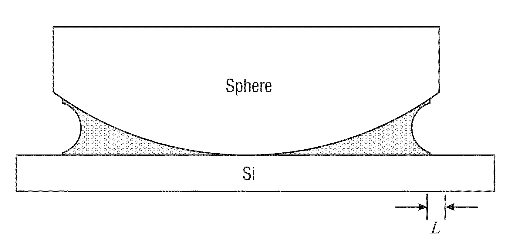
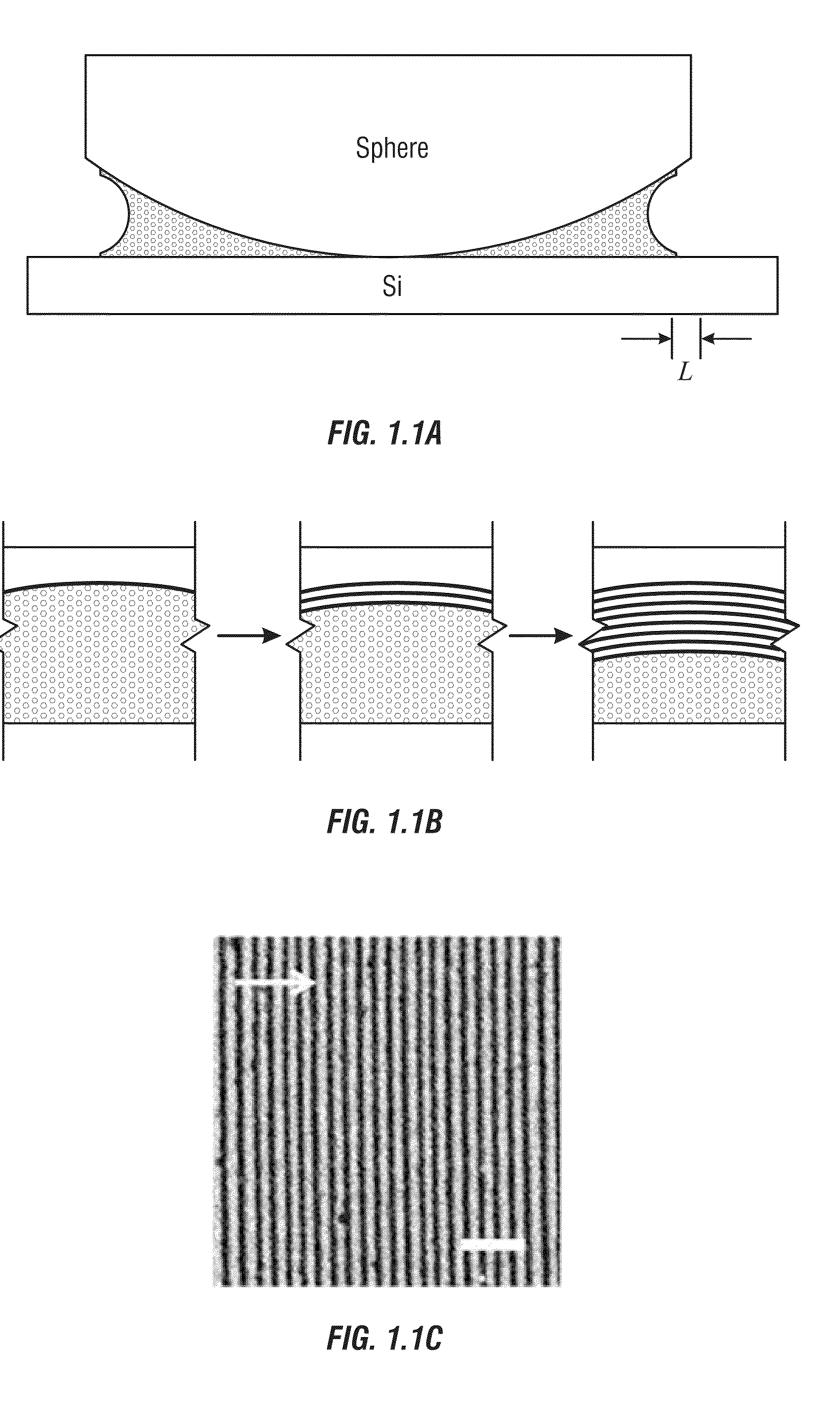
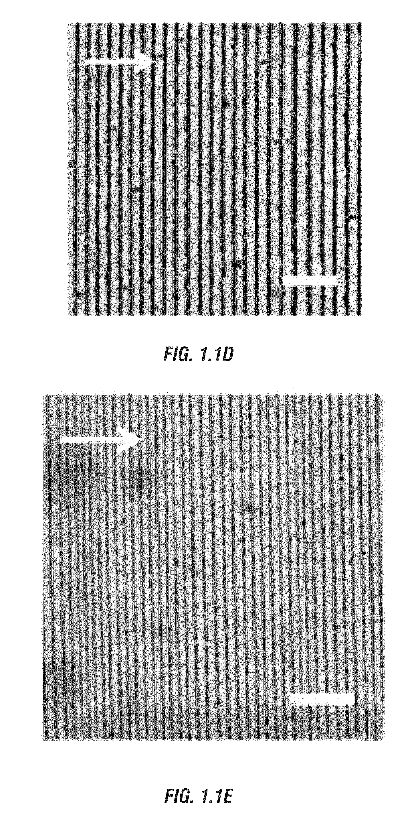
[0013]The invention pertains to the use of droplet evaporation techniques by constraining a droplet in confined geometry consisting of a spherical lens in contact with a flat substrate (i.e., sphere-on-flat geometry). The sphere-on-flat geometry renders the formation of very regular small-scale structures of residual solute after solvent evaporation. The droplets comprise a solution of a solvent and a solute. By selection and control of one or more parameters from a set of parameters found to affect the evaporation process, various characteristics of the resulting structures can be controlled. One set of parameters comprises solvent effect, concentration effect, solute molecular weight (MW) effect, interfacial interaction effect (i.e., the interfaction between solute and substrate). Another parameter relates to variation of shape of the sphere by selection and manipulation of the components of the droplet solution and the evaporation process.
[0014]Another aspect of the invention pertains to nature of the solute used in the solution. Different solutes produce different structures and different functional structures. One example is polymers. Use of homopolymers can produce certain regular shapes. Use of certain homopolymers can produce structures of different shapes or characteristics. Two examples of homopolymers are polystyrene (PS) and poly(methyl methacryalate) (PMMA). Another example is diblock copolymer. A still further example is semicrystalline polymer.
[0015]Another aspect of the invention is use of nanomaterials as or in the solute. An example is the use of nanoparticles. By selection of process parameters, the nanoparticles can self-assemble into regular ordered structures.
[0016]Another aspect of the invention relates to self-assembly, in hierarchical order, of nanomaterials or nanostructures relative to the small-scale ordered structures formed during evaporation of the solution. For example, small nano-scale structures (e.g. nanocylinders) can form hierarchically ordered structures over a multi-length scale that are formed from evaporation by selection of certain process parameters and appropriate solution components (e.g., diblock copolymer and nanoparticles). On the other hand, certain process steps can introduce nanomaterials into the micro-scale ordered structures.
[0017]Another aspect of the invention relates to use of the droplet evaporation techniques to create templates for functional uses. An example is creation of regularly ordered micro-scale structures that can either be applied to a functional substrate, or could be coated with a functional material. The ordered micro-scale structures form a template for the functional materials. An example of the functional material is an electrically conductive metal.

Problems solved by technology

However, fabrication of well-ordered structures at the micro- and sub-micro-scale is difficult because of the small feature sizes involved.
Also, fabrication of such small-scale structures for useful functions is difficult.
Present techniques tend to be complex and interactive.
Many lack repeatability or accuracy in regularity of shapes of the structures they produce.
With such traditional techniques, an iterative, multi-step procedure is required, making the process more complex and less reliable.
Lithography is also very time consuming and expensive.
However, the flow instabilities within the evaporating droplet often result in irregular dissipative structures, e.g. stochastic “coffee ring” shapes.
Evaporation-induced self-assembly, in general, gives rise to stochastic dissipative structures due to lack of control over complex evaporation processes and associated capillary flow.

Method used


Image

  • Drying-mediated self-assembly of ordered or hierarchically ordered micro- and sub-micro scale structures and their uses as multifunctional materials
  • Drying-mediated self-assembly of ordered or hierarchically ordered micro- and sub-micro scale structures and their uses as multifunctional materials
  • Drying-mediated self-assembly of ordered or hierarchically ordered micro- and sub-micro scale structures and their uses as multifunctional materials

Examples


example 1

REFERENCES FOR EXAMPLE 1

[0067][1] G. M. Whitesides, B. Grzybowski, Science 2002, 295, 2418.[0068][2] T. Thurn-Albrecht, J. Schotter, C. A. Kastle, N. Emley, T. Shibauchi, L. Krusin-Elbaum, K. Guarini, B. C. T., M. T. Tuominen, T. P. Russell, Science 2000, 290,[0069][3] V. V. Tsukruk, H. Ko, S. Peleshanko, Phys. Rev. Lett. 2004, 92, 065502.[0070][4] H. Ko, V. V. Tsukruk, Nano Lett. 2006, 6, 1443.[0071][5] Y. Lin, A. Boker, J. He, K. Sill, H. Xiang, C. Abetz, X. Li, J. Wang, T. Emrick, S. Long, Q. Wang, A. Balazs, T. P. Russell, Nature 2005, 434, 55.[0072][6] M. Gleiche, L. F. Chi, H. Fuchs, Nature 2000, 403, 173.[0073][7] J. Huang, F. Kim, A. R. Tao, S. Connor, P. D. Yang, Nature Mater 2005, 4, 896.[0074][8] A. M. Kalsin, M. Fialkowski, M. Paszewski, S. K. Smoukov, K. J. M. Bishop, B. A. Grzybowski, Science 2006, 312, 420.[0075][9] R. D. Deegan, O. Bakajin, T. F. Dupont, G. Huber, S. R. Nagel, T. A. Witten, Nature 1997, 389, 827.[0076][10] R. D. Deegan, O. Bakajin, T. F. Dupont, G. H...

example 2

REFERENCES FOR EXAMPLE 2

[0125]1. Nguyen, V. X.; Stebe, K. J. Phys. Rev. Lett. 2002, 88, 164501.[0126]2. Bormashenko, E.; Pogreb, R.; Musin, A.; Stanevsky, O.; Bormashenko, Y.; Whyman, G.; Barkay, Z. J. Coll. Interface Sci. 2006, 300, 293.[0127]3. Bormashenko, E.; Pogreb, R.; Musin, A.; Stanevsky, O.; Bormashenko, Y.; Whyman, G.; Gendelman, O.; Barkay, Z. J. Coll. Interface Sci. 2006, 297, 534.[0128]4. de Gennes, P. G. Eur. Phys. J. E 2001, 6, 421.[0129]5. Karthaus, O.; Grasjo, L.; Maruyama, N.; Shimomura, M. Chaos 1999, 9, 308.[0130]6. Hu, H.; Larson, R. G. Langmuir 2005, 21, 3963.[0131]7. Cazabat, A. M.; Heslot, F.; Troian, S. M.; Carles, P. Nature 1990, 346, 824.[0132]8. Yabu, H.; Shimomura, M. Adv. Funct. Mater. 2005, 15, 575.[0133]9. Rabani, E.; Reichman, D. R.; Geissler, P. L.; Brus, L. E. Nature 2003, 426, 271.[0134]10. Lin, Z. Q.; Granick, S. J. Am. Chem. Soc. 2005, 127, 2816.[0135]11. Xu, J.; xia, J.; Hong, S. W.; Lin, Z. Q.; Qiu, F.; Yang, Y. L. Phys. Rev. Lett. 2006, 96, 0...

example 3

REFERENCES FOR EXAMPLE 3

[0172][1] Y. Lin, A. Boker, J. He, K. Sill, H. Xiang, C. Abetz, X. Li, J. Wang, T. Emrick, S. Long, Q. Wang, A. Balazs, T. P. Russell, Nature 2005, 434, 55.[0173][2] M. Gleiche, L. F. Chi, H. Fuchs, Nature 2000, 403, 173.[0174][3] J. Huang, F. Kim, A. R. Tao, S. Connor, P. D. Yang, Nature Mater 2005, 4, 896.[0175][4] R. D. Deegan, O. Bakajin, T. F. Dupont, G. Huber, S. R. Nagel, T. A. Witten, Nature 1997, 389, 827.[0176][5] R. D. Deegan, Phys. Rev. E 2000, 61, 475.[0177][6] R. D. Deegan, O. Bakajin, T. F. Dupont, G. Huber, S. R. Nagel, T. A. Witten, Phys. Rev. E 2000, 62, 756.[0178][7] O. Karthaus, L. Grasjo, N. Maruyama, M. Shimomura, Chaos 1999, 9, 308.[0179][8] E. Rabani, D. R. Reichman, P. L. Geissler, L. E. Brus, Nature 2003, 426, 271.[0180][9] Z. Mitov, E. Kumacheva, Phys. Rev. Lett. 1998, 81, 3427.[0181][10] E. Adachi, A. S. Dimitrov, K. Nagayama, Langmuir 1995, 11, 1057.[0182][11] L. Shmuylovich, A. Q. Shen, H. A. Stone, Langmuir 2002, 18, 3441.[0183]...


PUM

PropertyMeasurementUnit
diameteraaaaaaaaaa
diameteraaaaaaaaaa
widthaaaaaaaaaa

Abstract

Methods, apparatus, and systems of fabricating ordered or hierarchically ordered small-scale structures (e.g. micro- or sub-micro size) without the need for lithographic techniques or external fields. The methods use irreversible solvent evaporation to deposit the solute on a surface. A spherical lens is brought down into contact with the droplet. By selection and control of one or more relevant parameters, various characteristics or features of the resulting structures can be controlled. Nano-scale structures or materials can be formed or included in the micro- or sub-micro-scale formed structures. The nano-scale structures or materials can self-assembly in hierarchical order by selection and control of certain process parameters.

Description

CROSS REFERENCE TO RELATED APPLICATIONS[0001]This application claims priority under 35 U.S.C. § 119 to a provisional application U.S. Ser. No. 60 / 902,464 filed Feb. 21, 2007, herein incorporated by reference in its entirety.Table of ContentsI.BACKGROUND OF INVENTION2A.Field of the Invention2B.Problems in the Art2II.SUMMARY OF THE INVENTION3III.BRIEF SUMMARY OF THE DRAWINGS5IV.DETAILED DESCRIPTION OF EXEMPLARY6EMBODIMENTSA.Overview6B.Exemplary Methodology in General6C.Specific Examples81. Example 1102. Example 2193. Example 3304. Example 4405. Example 5846. Example 6967. Example 71048. Example 8113D.Options and Alternatives127V.CLAIMS129VI.ABSTRACT OF THE DISCLOSURE134GRANT REFERENCE[0002]This invention was made with government support under grant number CBET-0730611 awarded by the National Science Foundation. The government has certain rights in the invention.I. BACKGROUND OF INVENTION[0003]A. Field of the Invention[0004]The present invention relates to methods, apparatus, and syste...

Claims


Application Information

Patent Timeline
Patent Type & Authority Applications(United States)
IPC IPC(8): B28B1/29
CPCB81B2207/056B82Y30/00B81C2201/0149B81C1/00031
Inventor LIN, ZHIQUN
Owner IOWA STATE UNIV RES FOUND
Why Eureka
Try Eureka