Led lighting system

a technology of led lighting and led light, applied in the field of led lighting systems, can solve the problems of inefficient energy use of incandescent bulbs including halogen bulbs, plasma-based fluorescents, frequent replacement, etc., and achieve the effect of reducing the nominal current of the array

Active Publication Date: 2009-01-22
NG WINNIE LAI LING
View PDF9 Cites 73 Cited by
  • Summary
  • Abstract
  • Description
  • Claims
  • Application Information

AI Technical Summary

Benefits of technology

[0033]One example of an array state that is sensed is the amount of electric current passing through the array. Another example is temperature, in which case the array state circuitry preferably includes

Problems solved by technology

However, incandescent bulbs including halogen bulbs, and to a lesser extent even plasma-based fluorescent, are generally inefficient in terms of energy use and have relatively short lifetimes, which leads to frequent replacement.
They are therefore direct-current (DC) devices and are easily damaged by excessive reverse voltage, forward current, or too high operating temperature.
The resulting high temperature can instantly destroy an LED.
Because the LEDs are usually packed together to form a single LED lighting system in a confined space, heat dissipation is limited.
Without this optimization, LED lighting systems either under-perform, that is, they do not produce the lumens-per-watt they could, or are under-designed, that is, they must operate outside their safe operating regions.
Further, line voltage components that would be required to compensate for these problems are usually rather large and more expensive than their lower voltage counterparts.
One approach is to use a step-down transformer to lower the line voltage before rectifying the AC voltage source; however, line voltage step-down transformers are even bigger than line voltage components.
An alternat

Method used


Image

  • Led lighting system
  • Led lighting system
  • Led lighting system

Examples


Embodiment Construction

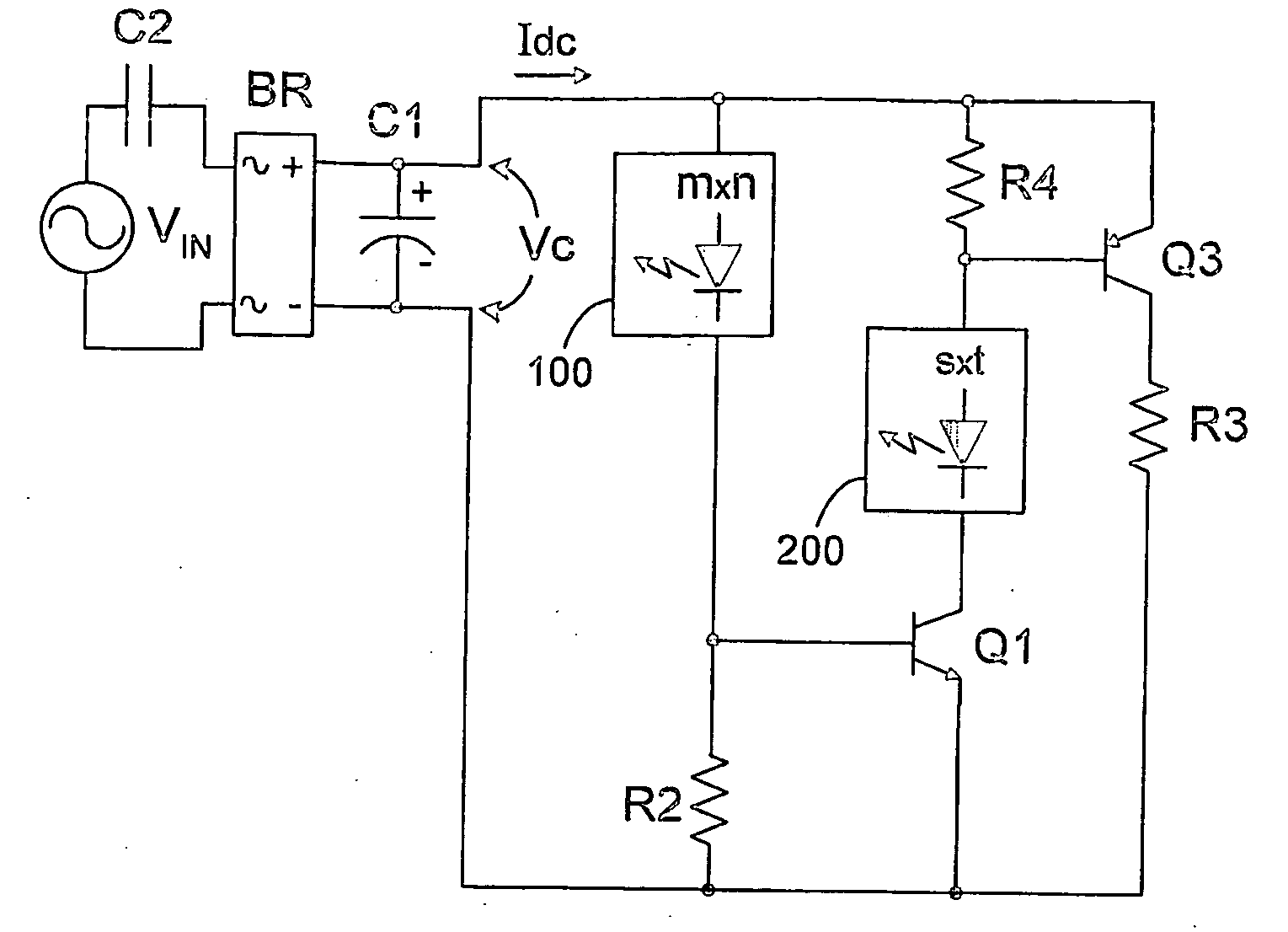
[0037]In broadest terms, the various aspects of the invention described below generally involve additional, secondary circuitry connected in parallel with an m-by-n array 100 of LEDs in order to provide more efficient use, in one or more ways, of the energy applied to drive the LED array. This additional circuitry operates to maintain the current through the array substantially constant. The invention may also be used to efficiently implement a system based on an array of laser diodes. The invention is described below with reference to LEDs merely for the sake of simplicity—every reference to an LED may thus be assumed to apply equally to a laser diode.

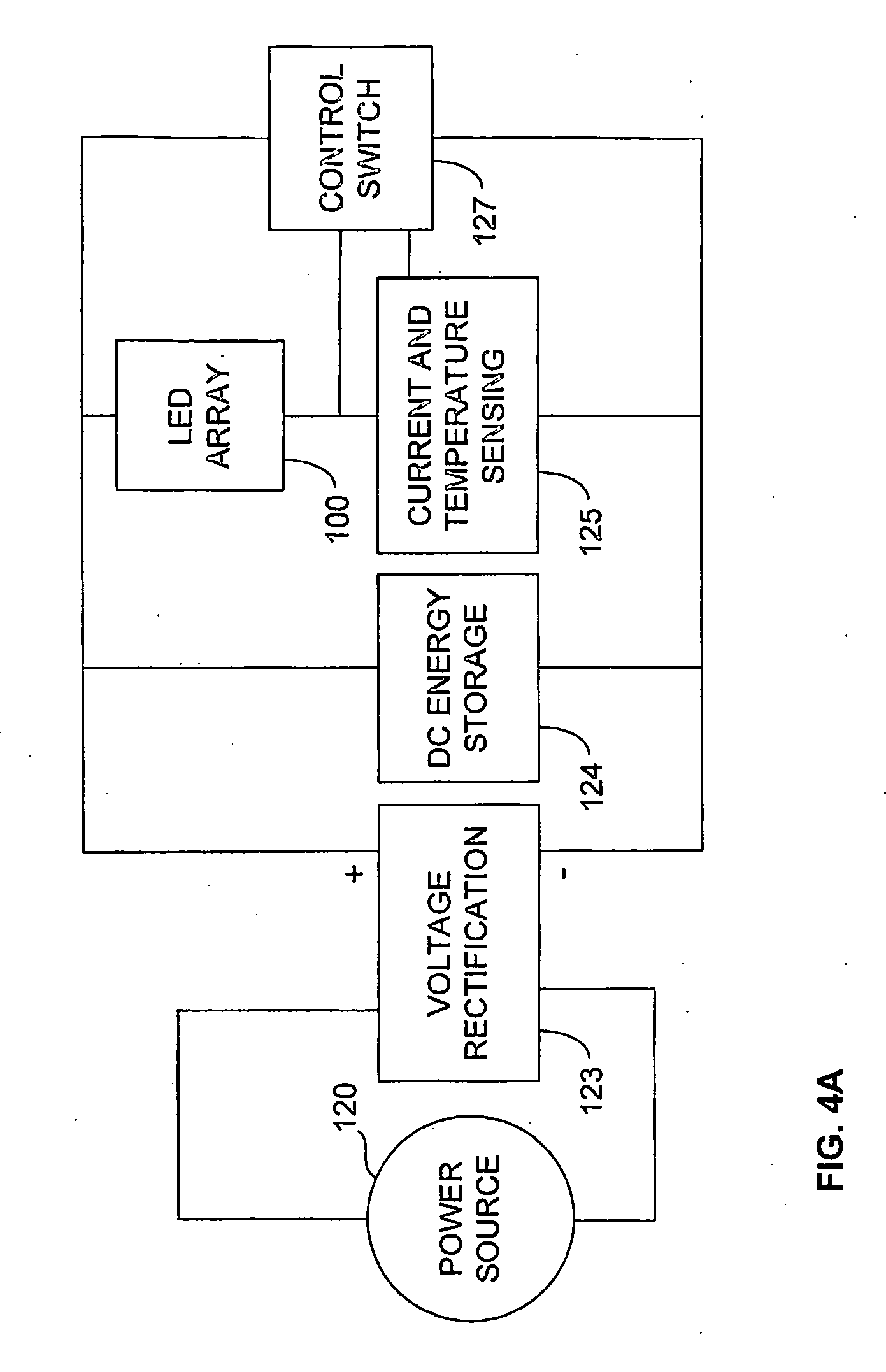
[0038]FIGS. 4A-4D are block diagrams of a progression of embodiments of the invention that use an AC power source 120 to drive at least the main LED array 100. The embodiment shown in FIG. 4A has, in addition to voltage rectification 123 and DC energy storage 124, the LED array 100 and current- and temperature sensing circuitry 125 in...


PUM


Abstract

A lighting system has an array (100) of at least one light-emitting solid-state element such as a light-emitting diode (LED) or a laser diode. A voltage source (10), which may supply either alternating or direct current, energizes the array. Array state circuitry (125; Q2, R2), electrically connected in series with the array (100), senses at least one state of the array, such as the amount of current passing through the array, or temperature. Secondary circuitry (127; R1, Q1; 200, 201, 202; 200, R4, Q1; 126, 127) is connected in parallel with the array (100). A switching component (Q1; Q1, Q3; 202) adjusts the current passing through the secondary circuitry in accordance with the sensed state of the array such that current through the array is maintained substantially constant. A third, parallel, excess current shunt path may also be provided, in which case so is excess current shunt circuitry, which senses current flowing in the secondary circuitry and shunts current in the secondary circuitry in excess of an excess current threshold to the excess current shunt path, whereby overflow current above a first threshold for the array (100) is shunted away from the array and excess current above a second threshold is shunted from the secondary circuits to the excess current shunt circuitry. A wide-angle mounting arrangement is also provided for the array.

Description

TECHNICAL FIELD[0001]This invention relates to lighting systems that use multiple light-emitting diodes (LEDs) or laser diodes.DESCRIPTION OF THE RELATED ART[0002]There has been a need for more and more efficient lighting since the only man-made lighting source was fire. Solid-state physics has provided several breakthroughs, however, that will probably change the principle of operation of almost all lighting systems in common use.LEDs vs. Incandescent[0003]Incandescent light bulbs are commonly used for indicator lamps, task lamps, general lighting, decorative lamps, warning lamps, traffic lamps and the like. However, incandescent bulbs including halogen bulbs, and to a lesser extent even plasma-based fluorescent, are generally inefficient in terms of energy use and have relatively short lifetimes, which leads to frequent replacement. Typically, less than 2% of the electrical energy going into an incandescent light bulb is transformed to visible light energy, the rest being converte...

Claims


Application Information

Patent Timeline
IPC IPC(8): H05B37/02H01L33/00H05B44/00
CPCY02B20/343H05B33/0812H05B45/397Y02B20/30H05B45/395
Inventor NG, JAMES K.
Owner NG WINNIE LAI LING
Why Eureka
Try Eureka