
Sensor device for measuring the compression travel and/or the compression rate of wheels and/or axles of vehicles

Inactive Publication Date: 2009-01-22
KNORR-BREMSE SYST FUER NUTZFAHRZEUGE GMBH
View PDF38 Cites 39 Cited by
  • Summary
  • Abstract
  • Description
  • Claims
  • Application Information

AI Technical Summary

Benefits of technology

[0007]Such radar sensors may be characterized by a relatively high imperviousness to environmental conditions such as, for instance, temperature or pressure changes and decontamination. Furthermore, radar technology which are already in use in commercial vehicles in ACC systems (adaptive cruise control), which measure the distance of a vehicle with respect to a vehicle driving in front in a contactless manner, may be implemented so that the sensors may be relatively cost-effective.
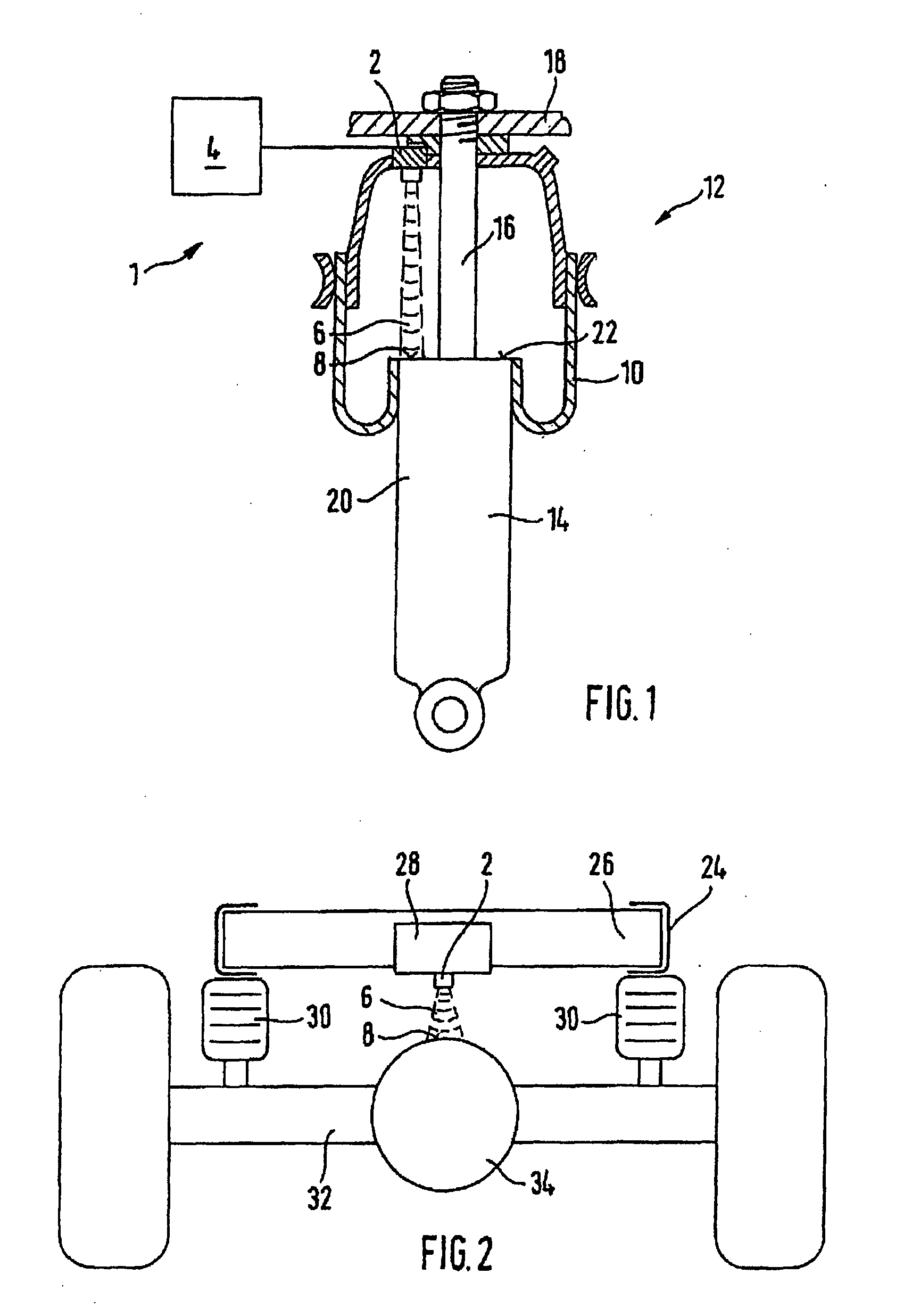
[0010]In another example variant of this embodiment, the radar sensor may be disposed inside or on a housing of a level control valve fixedly mounted on the frame or undercarriage of an air suspension system. A portion of an outer surface of a housing, lying opposite the sensor, of a differential gear which is fixed in place on the axle may form the reference or reflection surface. This not only saves space but may also dispense with the necessity of providing a separate receptacle for the wheel sensor on the frame.
[0012]In an example embodiment of the present invention, at least a portion of the radar sensor may be disposed within an air-suspension bellows of an air suspension element fixedly mounted on the frame or undercarriage, and the reference or reflection surface may be formed by a compressing surface of the air suspension bellows pointing to the interior of the air suspension bellows. This may have the advantage that the air suspension bellows provide special protection against contamination to both the sensor and the reference or reflection surface.

Problems solved by technology

A disadvantage of these systems lies in the often delicate lever-type mechanism, which can be damaged by falling rocks, for instance.
Loss of the automatic-level control means a total failure of the vehicle and entails high breakdown costs, in particular if commercially utilized vehicles are involved.
Here, it has shown to be disadvantageous that the measuring accuracy of ultrasonic sensors is heavily dependent upon environmental conditions such as the outside temperature, the ambient pressure, as well as the degree of soiling of the sensor surfaces.

Method used


Image

  • Sensor device for measuring the compression travel and/or the compression rate of wheels and/or axles of vehicles
  • Sensor device for measuring the compression travel and/or the compression rate of wheels and/or axles of vehicles
  • Sensor device for measuring the compression travel and/or the compression rate of wheels and/or axles of vehicles

Examples


Embodiment Construction

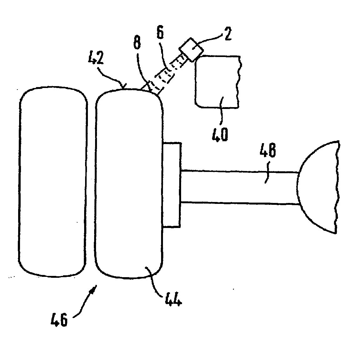
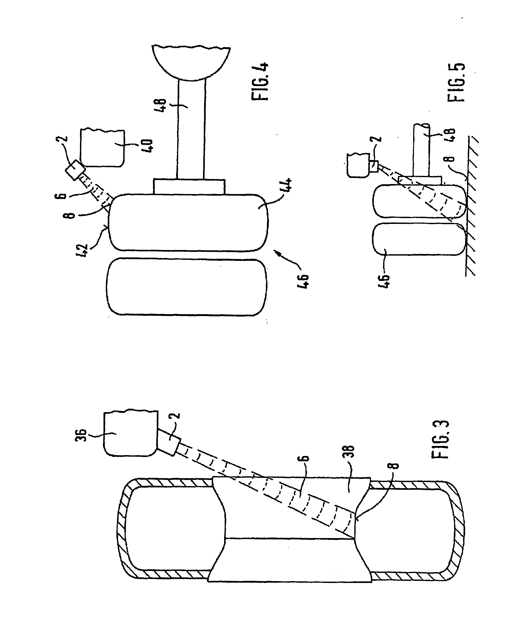
[0021]The sensor device, overall denoted by 1 in FIG. 1, may be utilized to measure the compression travel and / or the compression rate of wheels and / or axles of commercial vehicles, and, according to an example embodiment of the present invention, may include a radar sensor 2 known per se from, for instance, the Kraftfahrtechnisches Handbuch (Automotive Handbook) of Robert Bosch GmbH, 24th edition, p. 141 / 142. The sensor device 1 may also include a microcomputer-based, electronic evaluation device 4.

[0022]The measuring principle may be based on the propagation time measurement or propagation-speed measurement of an electromagnetic radar beam 6 emitted by a transmitter of radar sensor 2, which may be reflected at a reference or reflection surface 8 of a compressing or decompressing element and recorded by a receiver of radar sensor 2. Radar beams 6 reflected by reference or reflection surface 8 may be analyzed in evaluation device 4 with regard to propagation time, Doppler shift and ...


PUM


Abstract

A sensor device for measuring the compression travel and / or the compression rate of wheels and / or axles of vehicles, in particular of commercial vehicles, may include at least one sensor measuring in a contactless manner. The sensor device may include a radar and / or high-frequency sensor generating a beam, which is emitted and received after reflection at a reference and reflection surface.

Description

FIELD OF THE INVENTION[0001]The present invention relates to a sensor device for measuring the compression travel and / or the compression rate of wheels and / or axles of vehicles, in particular of commercial vehicles, the sensor device including at least one sensor measuring in a contactless manner.BACKGROUND INFORMATION[0002]Electronic vehicle systems require the compression travel of individual axles or wheels as a measured variable. Among such systems are, in particular, systems for automatic level control in the case of pneumatically suspended vehicles.[0003]Conventional sensor devices convert the compression travel into a rotary motion by means of a lever-type mechanism, and the angle of rotation is measured with the aid of angular-position sensors such as rotary potentiometers. A disadvantage of these systems lies in the often delicate lever-type mechanism, which can be damaged by falling rocks, for instance. Loss of the automatic-level control means a total failure of the vehic...

Claims


Application Information

Patent Timeline
IPC IPC(8): G01S13/88
CPCB60G17/0165B60G17/01933B60G2204/11B60G2204/111B60G2204/112G01S13/88B60G2204/115B60G2401/15B60G2401/17B60G2401/174B60G2401/176B60G2204/113
Inventor HECKER, FALK
Owner KNORR-BREMSE SYST FUER NUTZFAHRZEUGE GMBH
Learn More