Method and apparatus for anti-islanding of distributed power generation systems

a distributed power generation and anti-islanding technology, applied in the direction of emergency protective circuit arrangement, multiple dynamo-electric motor speed regulation, process and machine control, etc., can solve the problems of rapid depletion of fossil energy reserves currently being used to generate electricity, inconvenient installation, and inability to meet the needs of power generation

Inactive Publication Date: 2009-01-22
ENPHASE ENERGY
View PDF17 Cites 132 Cited by
  • Summary
  • Abstract
  • Description
  • Claims
  • Application Information

AI Technical Summary

Problems solved by technology

Due to the high cost of installation, solar panels were not an economical choice for generating power unless no other power options were available.
However, the worldwide growth of energy demand is leading to a durable increase in energy cost.
In addition, it is now well established that the fossil energy reserves currently being used to generate electricity are rapidly being depleted.
Under some conditions, a grid-connected DG system may become disconnected from the utility grid, resulting in a potentially dangero

Method used


Image

  • Method and apparatus for anti-islanding of distributed power generation systems
  • Method and apparatus for anti-islanding of distributed power generation systems
  • Method and apparatus for anti-islanding of distributed power generation systems

Examples


Embodiment Construction

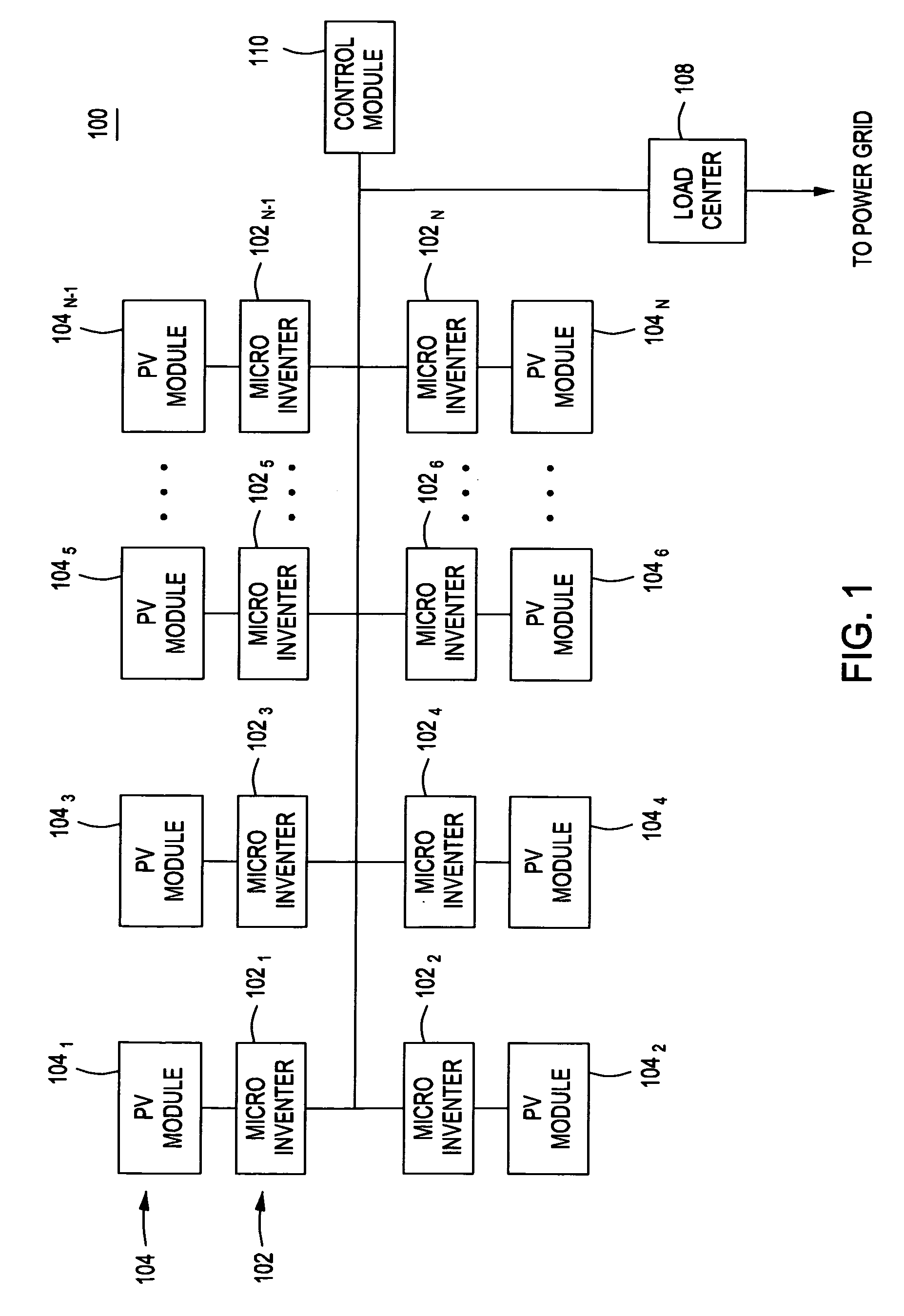
[0020]FIG. 1 is a block diagram of a system 100 for distributed generation (DG) in accordance with one or more embodiments of the present invention. This diagram only portrays one variation of the myriad of possible system configurations. The present invention can function in a variety of distributed power generation environments and systems.

[0021]The system 100 comprises a plurality of micro-inverters 1021, 1022 . . . 102n, collectively referred to as micro-inverters 102, a plurality of PV modules 1041, 1042 . . . 104n, collectively referred to as PV modules 104, an AC bus 106, a load center 108, and an array control module 110.

[0022]Each micro-inverter 1021, 1022 . . . 102n is coupled to a PV module 1041, 1042 . . . 104n, respectively. The micro-inverters 102 are further coupled to the AC bus 106, which in turn is coupled to the load center 108. The load center 108 houses connections between incoming power lines from a commercial power grid distribution system and the AC bus 106. ...


PUM


Abstract

A method and apparatus for anti-islanding of distributed power generation systems having an inverter comprising a phase locked loop (PLL), a phase shift generator for injecting a phase shift into the PLL during at least one sample period, and a phase error signature monitor for monitoring at least one phase error response of the PLL during the at least one sample period.

Description

CROSS-REFERENCE TO RELATED APPLICATIONS[0001]This application claims benefit of U.S. provisional patent application Ser. No. 60 / 959,644, filed Jul. 16, 2007, which is herein incorporated by reference.BACKGROUND OF THE INVENTION[0002]1. Field of the Invention[0003]Embodiments of the present disclosure generally relate to a method and apparatus for anti-islanding of distributed power generation systems.[0004]2. Description of the Related Art[0005]Solar panels have historically been deployed in mostly remote applications, such as remote cabins in the wilderness or satellites, where commercial power was not available. Due to the high cost of installation, solar panels were not an economical choice for generating power unless no other power options were available. However, the worldwide growth of energy demand is leading to a durable increase in energy cost. In addition, it is now well established that the fossil energy reserves currently being used to generate electricity are rapidly be...

Claims


Application Information

Patent Timeline
IPC IPC(8): H02H3/44
CPCH02J2003/388Y02E10/563H02J3/383H02J3/388H02J2300/24H02J3/381Y02E10/56
Inventor FORNAGE, MARTINHASSAN-ALI, MUDHAFARBOLFAN, TIBOR
Owner ENPHASE ENERGY
Why Eureka
Try Eureka