Overvoltage protection device with improved leakage-current-interrupting capacity

a protection device and leakage current technology, applied in the direction of excess voltage responsive arrangements, emergency protection arrangements for limiting excess voltage/current, electrical equipment, etc., can solve the problem that the leakage current may interfere with the sensitive electronic system downstream of the protection device, the capacitor charge suffers from a trigger lag effect, and the known protection devices cannot be completely efficient. the effect of no leakage curren

Inactive Publication Date: 2009-01-22
ABB FRANCE SAS
View PDF5 Cites 22 Cited by
  • Summary
  • Abstract
  • Description
  • Claims
  • Application Information

AI Technical Summary

Benefits of technology

[0011]The features provided by the present invention overcome the various previously-mentioned disadvantages and provide a new device for protecting an electrical installation against voltage surges, wherein the new device, in the absence of overvoltage, consumes substantially no leakage current.
[0012]A feature of the present invention is a device for protecting an electrical installation against overvoltage, wherein the device is equipped with a pre-triggering circuit that permits the arc striking voltage of the spark gap to be reduced.
[0013]Another feature of the present invention is a device for protecting electrical installations against overvoltage, wherein the device is equipped with a pre-trigger circuit designed to prevent, in the absence of voltage surges, the circulation of current in the protection device.

Problems solved by technology

Firstly, in the absence of an overvoltage, known protection devices are traversed by a leakage current that circulates in the pre-triggering circuit when powered at its permanent voltage. However, the existence of such a leakage current may interfere with the sensitive electronic systems downstream of the protection device, such as, for example, low power differential circuit breakers or insulation testing devices.
Furthermore, pre-triggering circuits that operate on the principle of a capacitor charge suffer from a trigger lag effect due to the charging time of the capacitor.
Consequently, known protection devices cannot be completely efficient and have a certain number of weaknesses, in particular, associated with the design of the pre-triggering circuit.

Method used


Image

  • Overvoltage protection device with improved leakage-current-interrupting capacity
  • Overvoltage protection device with improved leakage-current-interrupting capacity
  • Overvoltage protection device with improved leakage-current-interrupting capacity

Examples


Embodiment Construction

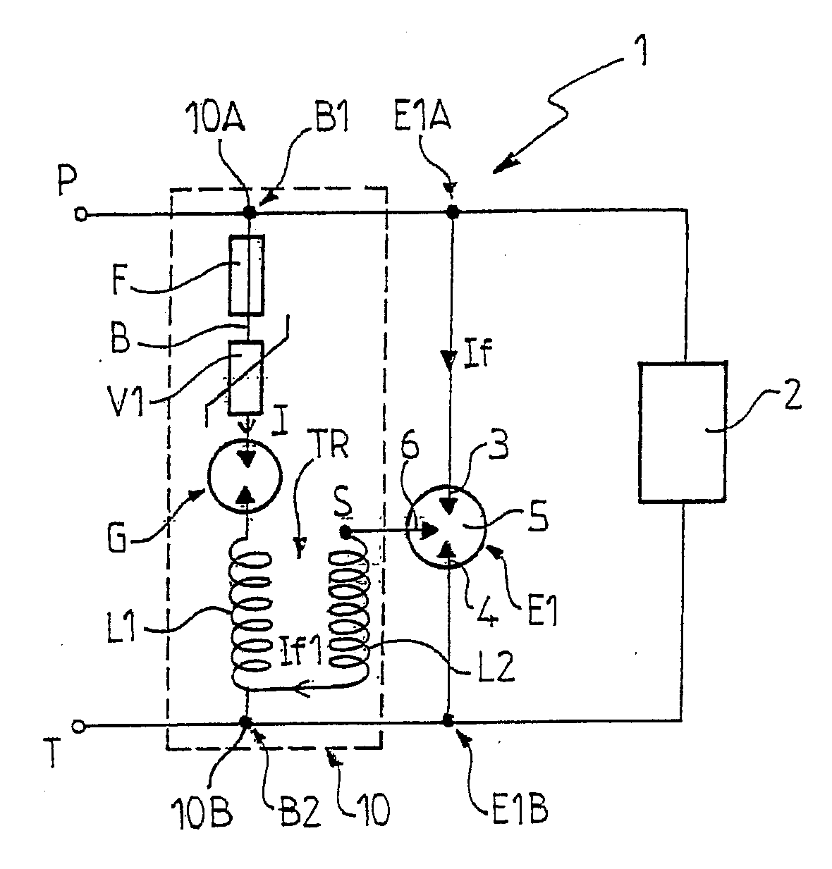
[0025]The overvoltage protection device in accordance with the present invention is designed to bypass the electrical equipment or installation to be protected.

[0026]For purposes of the present disclosure, the term “electrical installation” refers to any appliance or system likely to be subjected to voltage disturbances, in particular transient overvoltages due to lightning strikes. Such overvoltage protection devices are commonly referred to as “lightning arresters”.

[0027]The overvoltage protection device in accordance with the present invention is advantageously designed to be positioned between one phase of the installation to be protected and the earth (ground). Furthermore, it may be envisaged, without this being outside of the scope of the invention, that the device, instead of being connected between one phase of the installation and the earth, be connected between the neutral and the earth, between the phase of the installation and the neutral, or between two phases of the i...


PUM


Abstract

A device for protecting an electrical installation (2) against overvoltages, the device having a main spark-gap (E1) and a pre-triggering circuit (10) connected to the main spark-gap (E1) to control the firing of the main spark-gap in the event of any overvoltage. The pre-triggering circuit (10) has at least one voltage-interrupting element (G) which, in the off state, prevents current from passing through the pre-triggering circuit (10), so that, in the absence of an overvoltage, the leakage current consumed by the pre-triggering circuit (10) is essentially zero.

Description

PRIORITY CLAIM[0001]This patent application is a U.S. National Phase of International Application No. PCT / FR2005 / 001916, filed Jul. 25, 2005, which claims priority to French Patent Application No. 0408251, filed Jul. 26, 2004, the disclosures of which are incorporated herein by reference in their entirety.FIELD OF THE INVENTION[0002]The present invention relates to devices for protecting electrical equipment or installations against voltage disturbances such as surges, and in particular transient overvoltage due, for example, to lightning strikes. The present invention relates more specifically to a device for protecting an electrical installation against voltage surges, in particular transient overvoltage due to a lightning strike.BACKGROUND OF THE INVENTION[0003]Devices for protecting electrical installations against overvoltage are widely used and often designated as “lightning arresters”. Their essential purpose is to earth the lightning strike current and possibly clip the addi...

Claims


Application Information

Patent Timeline
Patent Type & Authority Applications(United States)
IPC IPC(8): H02H3/22H01T2/02H02H9/06
CPCH02H9/06H01T2/02
Inventor CREVENAT, VINCENT ANDRE LUCIEN
Owner ABB FRANCE SAS
Why Eureka
Try Eureka