Method of optimized gradient coil design

a gradient coil and design technology, applied in the field of new gradient coil design method, can solve the problems of worm bore or cold shield of the magnet eddy current induced in the worm bore or the magnetic shield, and is difficult to find a continuous solution

Inactive Publication Date: 2009-01-22
HITACHI MEDICAL SYSTEMS AMERICA INC
View PDF13 Cites 5 Cited by
  • Summary
  • Abstract
  • Description
  • Claims
  • Application Information

AI Technical Summary

Benefits of technology

[0018]The present invention relates to an improved method of discretization of the continuous current solution of a gradient coil design that allows satisfaction of the target field quality characteristics as well as other characteristics such as minimization of the energy / inductance, minimization of the residual eddy current effect, minimization of the thrust forces on the coil and cold shields, coil resistance thus the power dissipated by the coil, etc. The method of optimized gradient coil design can be applied to the design of axial or transverse gradient coils. The method of this invention includes the steps of defining at least one, and more commonly numerous performance characteristics of the desired gradient coil, concurrently varying discretization parameters to develop numerous possible hypothetical gradient coil designs, evaluating the designs to determine whether the defined performance characteristics are met by each design and selecting one design. The design selected will often be the design that offers the best design solution by meeting numerous, if not all of the defined performance characteristics.

Problems solved by technology

One of the problems in past methods of gradient coil design is the discretization procedure that approximates the continuous current densities by a number of current carrying conductors (step 4 of the above method).
It is sometimes difficult to find a continuous solution that satisfies the field quality characteristics within the FoV and where the net thrust force is nullified by constraint.
Depending on the magnet configuration the nullification of the thrust force can lead to an energy penalty or even to reversed current patterns on either the primary coil or the shield coil, which in fact leads to the energy / inductance penalty.
Another problem that arises in previous methods of gradient coil design is that eddy currents are induced in the worm bore or the cold shield of the magnet.
Eddy currents in the cold shield result in distortions of the images.
These significant forces on the cold shield may lead to the vibration of the cold shield and even quenching of the magnet.
In practice the latter is difficult to achieve (IP≠IS) because of the free parameters in the problem: the geometry of the coil is determined by the space available and usually is at premium.

Method used


Image

  • Method of optimized gradient coil design
  • Method of optimized gradient coil design
  • Method of optimized gradient coil design

Examples


Embodiment Construction

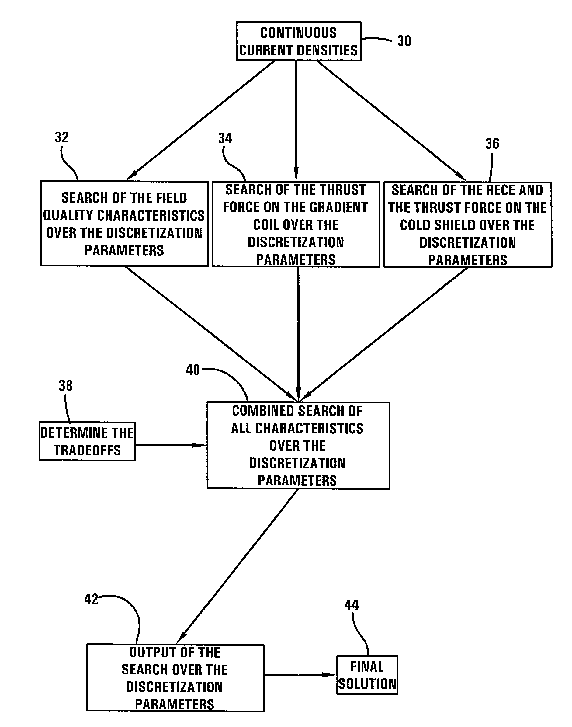
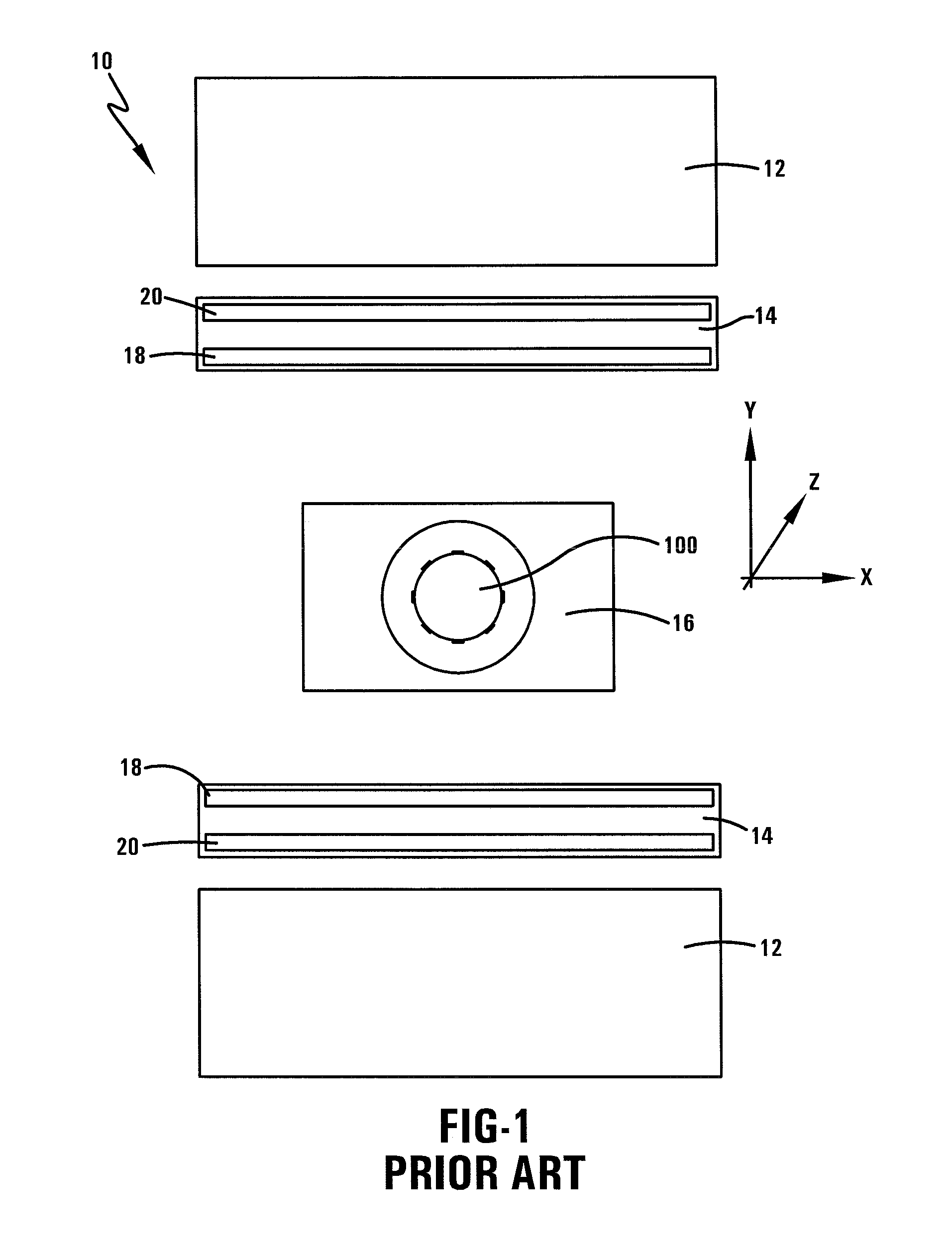
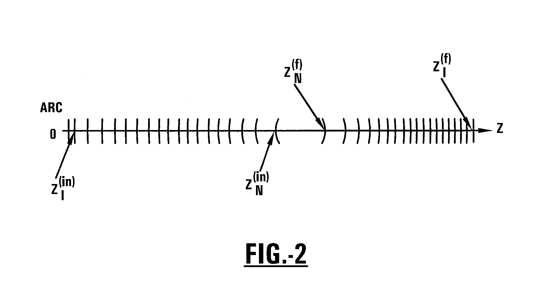
[0045]Referring now to the drawings wherein the showings are for purposes of illustrating numerous embodiments of the invention only and not for purposes of limiting the same, the figures illustrate the novel idea of an improved method of discretization of the continuous current solution of a gradient coil design.

[0046]The present invention puts forth an improved method of gradient coil design using an improved discretization process of the continuous current solution. The present invention applies to the design of both axial and transverse gradient coil design.

[0047]Axial Gradient Coil

[0048]The method of designing an axial gradient coil of embodiments of the invention, wherein the axial gradient coil having a primary coil and a shield coil for use in magnetic resonance imaging, includes defining at least one performance characteristic of the axial gradient coil, concurrently varying at least two parameters within at least one equation, wherein each result of the varied at least two...


PUM


Abstract

The present invention relates to a method of discretization of the continuous current solution of a gradient coil design that allows satisfaction of the target field quality characteristics as well as other characteristics such as minimization of the energy/inductance, minimization of the residual eddy current effect, minimization of the thrust forces on the coil and cold shields, coil resistance thus the power dissipated by the coil, etc. The method of optimized gradient coil design can be applied to the design of axial or transverse gradient coils. The method of this invention includes the steps of defining at least one, and more commonly numerous performance characteristics of the desired gradient coil, concurrently varying discretization parameters to develop numerous possible hypothetical gradient coil designs, evaluating the designs to determine whether the defined performance characteristics are met by each design and selecting one design.

Description

TECHNICAL FIELD[0001]The invention relates to a new method of gradient coil design for use in magnetic resonance imaging (MRI) for spatial encoding of the MRI signal. The invention more specifically relates to a new method of optimized gradient coil design for both transverse and axial gradient coil.BACKGROUND OF THE INVENTION[0002]Magnetic resonance imaging (MRI) is a medical diagnostic imaging technique used to diagnose many types of medical conditions. An MRI system includes a main magnet for generating a main magnetic field through an examination region. The main magnet is arranged such that its geometry defines the examination region. The main magnetic field causes the magnetic moments of a small majority of the various nuclei within the body to be aligned in a parallel or anti-parallel arrangement. The aligned magnetic moments rotate around the equilibrium axis with a frequency that is characteristic for the nuclei to be imaged. An external radiofrequency (RF) field applied by...

Claims


Application Information

Patent Timeline
Patent Type & Authority Applications(United States)
IPC IPC(8): G06F17/50
CPCG06F17/50G01R33/385G06F30/00
Inventor SHVARTSMAN, SHMARYU
Owner HITACHI MEDICAL SYSTEMS AMERICA INC
Why Eureka
Try Eureka