Method for manufacturing a rigid-flex circuit board

a manufacturing method and technology of rigid-flex circuit boards, applied in the field of printed circuit board (pcb) technology, can solve the problems of increasing production costs, time-consuming custom-made fixtures or molds, and risk of damaging the flex board

Inactive Publication Date: 2009-01-29
NAN YA PRINTED CIRCUIT BOARD CORPORATION
View PDF4 Cites 41 Cited by
  • Summary
  • Abstract
  • Description
  • Claims
  • Application Information

AI Technical Summary

Problems solved by technology

Because of the difficulty of precise control of the routing depth, the aforesaid mechanical depth-controlled routing technique for removing the redundancy rigid part above a bending area may have potential risks of damaging the flex board, particularly at the interface between the flex and rigid parts.
Further, expensive, custom-made fixtures or molds are ordinarily required in the mechanical depth-controlled routing process, thus increasing the production cost.
The custom-made fixtures or molds are also time-consuming, which decreases the production throughput.

Method used


Image

  • Method for manufacturing a rigid-flex circuit board
  • Method for manufacturing a rigid-flex circuit board
  • Method for manufacturing a rigid-flex circuit board

Examples


Embodiment Construction

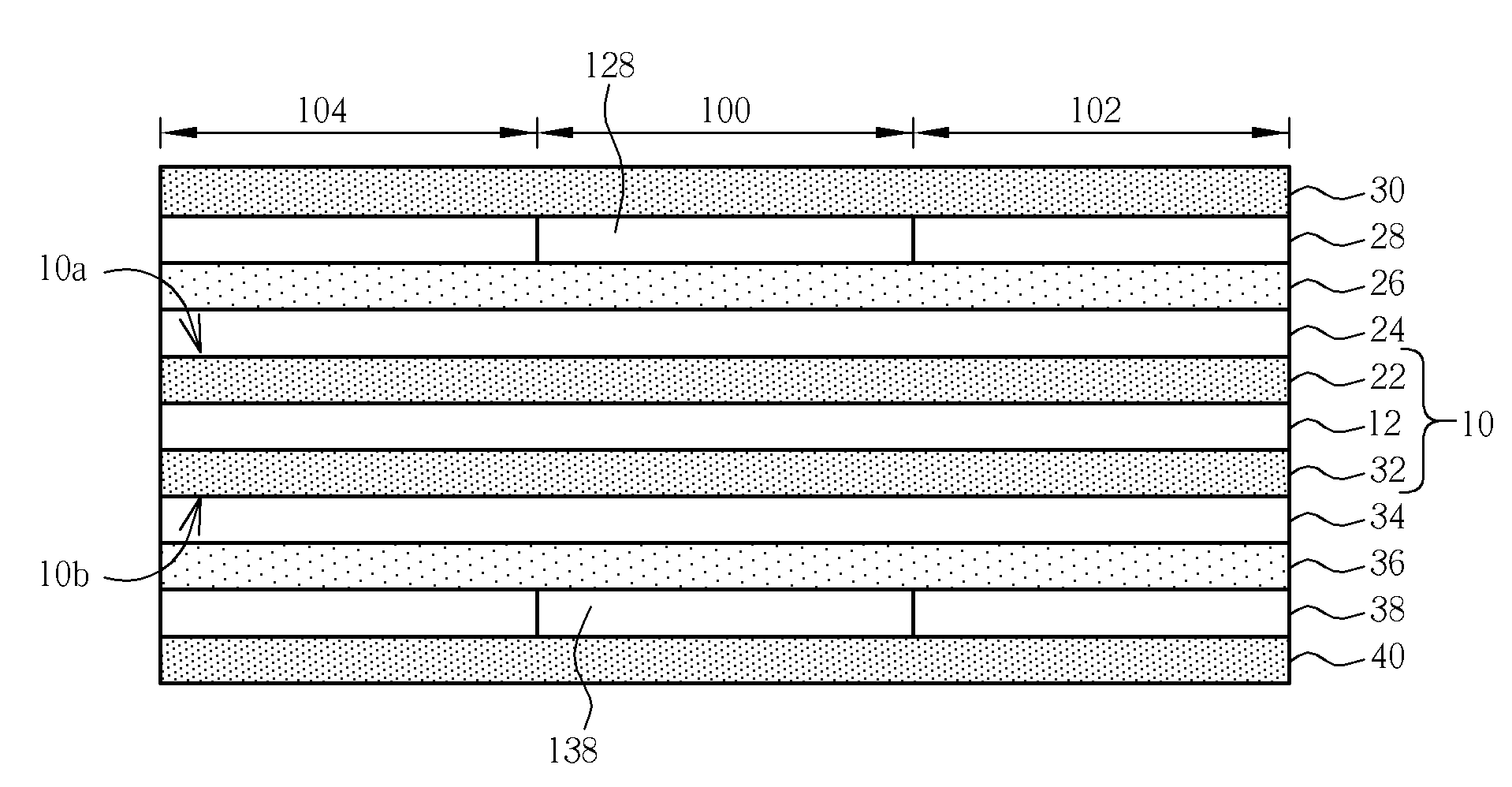
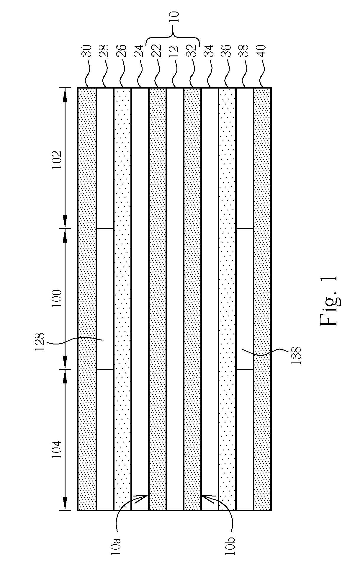
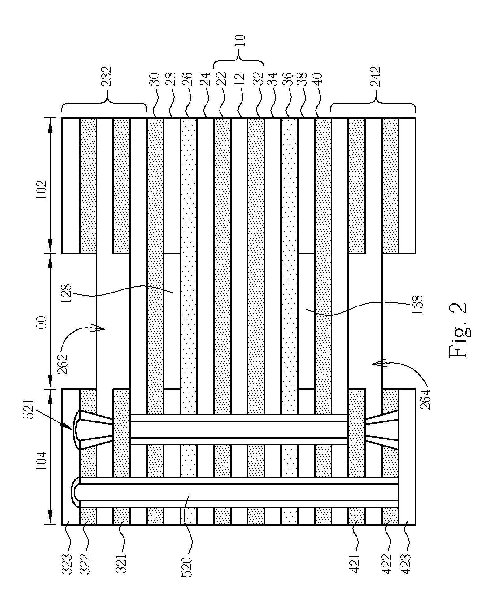
[0011]Please refer to FIGS. 1-7. FIGS. 1-7 are schematic diagrams illustrating the method for manufacturing a rigid-flex board in accordance with one preferred embodiment of this invention, wherein FIGS. 1-3 and 5-7 are cross-sectional views of the rigid-flex board, while FIG. 4 is a schematic top view showing the rigid-flex board after performing a second cutting process.

[0012]As shown in FIG. 1, a flex board 10 comprising an intermediate base layer 12, a copper circuit pattern layer 22 and a copper circuit pattern layer 32 is provided. The intermediate base layer 12 may be composed of dielectric materials. The dielectric materials may include but not limited to polyimide.

[0013]A protective cover layer 26 and a protective cover layer 36 are formed on the first side 10a and second side 10b of the flex board 10, respectively. The protective cover layers 26 and 36 may be composed of polyimide or any other suitable materials. The protective cover layers 26 and 36 protect the underlying...


PUM

PropertyMeasurementUnit
dielectricaaaaaaaaaa
perimeteraaaaaaaaaa
areaaaaaaaaaaa

Abstract

A method for manufacturing a rigid-flex board is disclosed. After the formation of each layer of the rigid-flex board, a laser-etched groove is formed at the interface between a rigid part and a bending area of the rigid-flex board. After the laser etching process, a circuit-board routing process is performed to remove materials along the sideward perimeter of the bending area. The exposed copper layer is then removed from inside the laser-etched groove. Thereafter, a redundancy rigid structure within the bending area is readily removed to expose the flex board within the bending area.

Description

BACKGROUND OF THE INVENTION[0001]1. Field of the Invention[0002]The present invention relates to the field of printed circuit board (PCB) technology. More particularly, the present invention relates to a method for manufacturing a rigid-flex circuit board.[0003]2. Description of the Prior Art[0004]Rigid-flex printed circuit boards or rigid-flex boards are known in the art, which allow integrated interconnection between several rigid boards. This technology helps to reduce the number of soldered joints and plug-in connections and also the number of wires and cables, thus improving quality and reliability. For this reason, the rigid-flex board has become firmly established in many sectors of industry, notably automotive, telecommunications, medical, sensor technology, mechanical engineering and military electronics.[0005]Typically, the fabrication of a rigid-flex board may start with a flex circuit board or flex board as core material. Rigid circuit board process such as build-up meth...

Claims


Application Information

Patent Timeline
Patent Type & Authority Applications(United States)
IPC IPC(8): H01B13/00
CPCH05K3/0035H05K3/06H05K3/4602H05K3/4652H05K2203/1476H05K2201/0909H05K2201/09127H05K2201/09536H05K2203/0228H05K3/4691
Inventor TSAI, TZONG-WOEILIN, YU-LUNHSU, HUNG-EN
Owner NAN YA PRINTED CIRCUIT BOARD CORPORATION
Why Eureka
Try Eureka