Image processing apparatus, image-taking system, image processing method and image processing program

a processing apparatus and image processing technology, applied in the field of image information processing technology, can solve the problems of large intensity, difficult to suppress unwanted diffract light across the entire visible light region, and difficult to apply to the element which comprises an image-taking optical system such as a camera lens, etc., and achieves the effects of high brightness, difficult visual recognition, and high quality

Inactive Publication Date: 2009-01-29
CANON KK
View PDF9 Cites 16 Cited by
  • Summary
  • Abstract
  • Description
  • Claims
  • Application Information

AI Technical Summary

Benefits of technology

[0018]It is an object of the present invention to provide image processing technology that enables a high quality image to be obtained from image information acquired by raking an image of an object with a particularly high brightness, by specifying an image which corresponds to an image produced by non-image forming light and subjecting that image to image processing to make the image difficult to recognize visually.
[0022]According to a still further aspect, this invention provides an image processing apparatus which processes an electronic image obtained by forming an image on a photoelectric conversion element by use of an optical system which includes a diffractive optical element. The image processing apparatus has a pixel detecting section which detects the positions of high brightness pixels having a brightness that is equal to or greater than a predetermined value in the electronic image, a deterioration detecting section which detects or estimates a generated amount of image-quality deteriorating components which were generated by a diffracting action of the diffractive optical element in the electronic image by taking the high brightness pixels as reference points, and a correcting section which removes or reduces image-quality deteriorating components generated in peripheral regions of the high brightness pixels on the basis of a generated amount obtained by the deterioration detecting part.

Problems solved by technology

Therefore, although there are cases where a contrivance is devised whereby a diffractive surface is rendered serrate to condense light only in an image-forming order, it is difficult to suppress unwanted diffracted light across an entire visible light region.
Accordingly, the practical application thereof as an element which comprises an image-taking optical system such as a camera lens has been difficult.
However, even when using a DO lens, when taking an image of an object of an extremely intense brightness (luminous energy), the intensity of unwanted diffracted light is raised by the intense brightness and results in a large intensity.
Thus, depending on the image-taking environment, the occurrence of flare images due to unwanted diffracted light is an unavoidable phenomenon.
However, in a practical DO lens, the image-forming order is sufficiently larger than the diffraction efficiency of unwanted orders, and thus unwanted diffracted light does not become visually noticeable in a taken image at a brightness where the brightness of an image produced by the image-forming order is not saturated.
Therefore, the technology proposed in the above publications is meaningless when using a practical DO lens for this type of image-taking.
Moreover, when flare resulting from unwanted diffracted light appears in a taken image even when using a practical DO lens, it indicates that the brightness of the image produced by the image-forming light is definitely saturated.
Thus, even if the technique proposed In the aforementioned patent literature is used, since the object image component itself cannot be accurately obtained because of brightness saturation, a flare component that is to be corrected cannot be estimated.
However, In practice it is extremely difficult to conduct image-taking almost simultaneously a plurality of times in a state where there is no means to know what level of exposure to use to suppress brightness saturation, and in particular, it is not a useful means for a moving object.
There is also a possibility that the exposure set in the image-taking apparatus will not be capable of suppressing brightness saturation.
Because of the above problems, for images which include highlights to the extent that unwanted diffracted light constitutes a problem, in reality it is not possible to take images in which the problem of brightness saturation is overcome with respect to the brightness distribution of the image-forming diffracted light unless the image is taken in a special environment, and this is not useful as a technique which eliminates unwanted diffracted light.

Method used


Image

  • Image processing apparatus, image-taking system, image processing method and image processing program
  • Image processing apparatus, image-taking system, image processing method and image processing program
  • Image processing apparatus, image-taking system, image processing method and image processing program

Examples


embodiment 1

[0061]FIG. 4 shows a system block diagram of a digital still camera as an image-taking system which includes an image processing apparatus as Embodiment 1 of this invention. In FIG. 4, arrows with a dotted line indicate the flow of processing instructions and arrows with a solid line indicate the flow of information.

[0062]The digital camera shown in FIG. 4 has an image-taking section 10, a controller 20, an electrical signal processing section 30, and an output image memory 40. Of these, the image-taking section 10 has an image-taking optical system 11 which includes a diffractive optical element which has a diffractive surface, and an image-pickup element 12 which is composed of a photoelectric conversion element such as a CCD sensor or CMOS sensor. The image-taking section 10 forms an image of an object image from the image-taking optical system 11 on a light-receiving surface of the image-pickup element 12, and outputs an electrical signal from the image-pickup element 12.

[0063]T...

embodiment 2

[0123]FIG. 14 shows a system block diagram of a computer as an image processing apparatus as Embodiment 2 of this invention. This computer comprises a CPU (controller) 50 which conducts calculational processing and driving instructions of the computer, an information input interface 60 which is responsible for incorporation of information from outside the computer, a processing instructions input interface 70 which allows the user to input instructions to conduct a predetermined processing into the computer, a hard disk 80 which stores various information and the operating system of the computer, a RAM 90 which temporarily stores information which is necessary when implementing operations in response to an instruction from the CPU 50, and an image display section 100 for displaying information such as an image or a GUI. These are connected to each other by a bus which transfers processing signals and various information.

[0124]This computer incorporates onto the hard disk 80 via the ...

embodiment 3

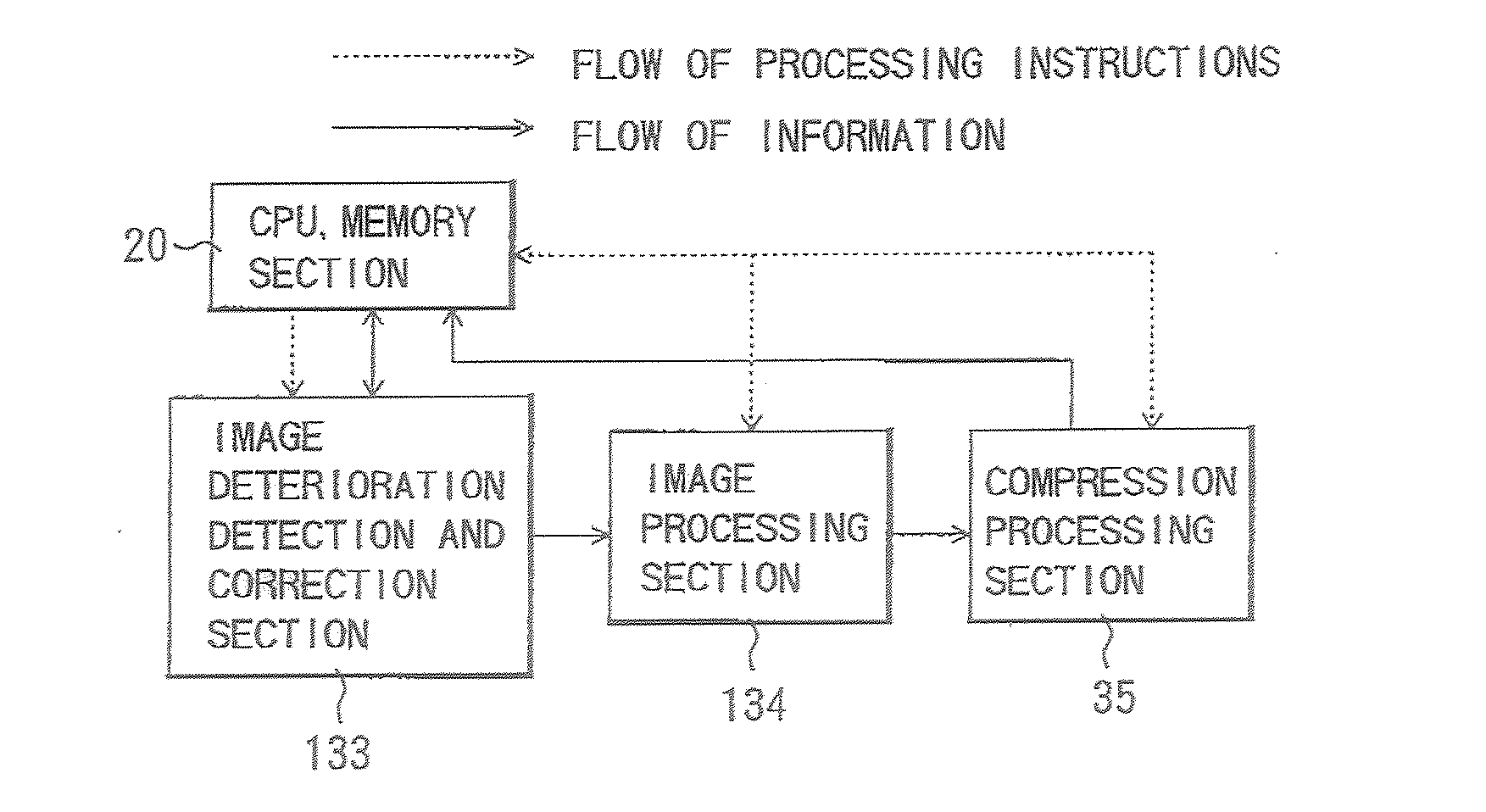
[0188]FIG. 20 and FIG. 22 show system block diagrams of a digital still camera as an image-taking system which includes an image processing apparatus as Embodiment 3 of this invention. In FIG. 20, arrows with a dotted line indicate the flow of processing instructions and arrows with a solid line indicate the flow of information. In FIG. 20 and FIG. 22, components which are common with Embodiment 1 have been assigned the same symbols as the corresponding components in FIGS. 4 and 6.

[0189]The image-taking system has an optical system 11 which includes a diffractive optical element, an image-taking section 10 which comprises an image-pickup element 12 which is composed by a photoelectric conversion element such as a CCD sensor or CMOS sensor, and a controller (CPU and memory) 20 which issues driving instructions for the overall image-taking system and also stores various information other than image information.

[0190]The image-taking system also has an electrical signal processing sect...


PUM


Abstract

An image processing apparatus is disclosed which can provide a high-quality image by specifying an image corresponding to an image resulting from non-image forming light in image information obtained by taking an image of an object having a high brightness and conducting image processing to make the image difficult to recognize visually. The image processing apparatus processes image information which includes a first image component which was responsive to an image-forming light and a second image component which was responsive to a non-image forming light. The image processing apparatus has an image acquiring section which acquires the image information and an edge processing section which conducts edge processing with respect to the image information to distinguish the second image component with respect to the first image component.

Description

BACKGROUND OF THE INVENTION[0001]1. Field of the Invention[0002]The present invention relates to processing technology for image information which includes a first image component which was responsive to an image-forming light and a second image component which was responsive to a non-image forming light, and more specifically to image processing technology to make a second image component inconspicuous.[0003]2. Description of the Related Art[0004]Optical elements which have a diffractive surface (diffractive optical elements) are elements which actively utilize the diffraction effect of light, and have an action which separates light that is incident on the diffractive optical element into a variety of diffraction orders or an action which condenses only light of a predetermined diffraction order, and the like.[0005]For example, characteristics oh a diffractive optical element designed to have a condensing action include a small thickness, a capability of generating an aspherical w...

Claims


Application Information

Patent Timeline
Patent Type & Authority Applications(United States)
IPC IPC(8): H04N5/217G06T5/00G06T7/40H04N5/228
CPCG06T7/408G06T2207/20192G06T5/003H04N5/217G06T7/90H04N23/81
Inventor FUKUMOTO, TOSHIHIRO
Owner CANON KK
Why Eureka
Try Eureka