Head gimbal assembly having balanced weight, disk drive unit with the same and manufacturing method thereof

a gimbal and balanced technology, applied in the direction of data recording, magnetic recording, instruments, etc., can solve the problems of adversely affecting the ability of the read/write head, the hga design inherently possesses some disadvantages, and the use of known technology becomes more and more difficult to quickly and accurately position the read/write, etc., to achieve the effect of improving the resonance performance, servo bandwidth, and tpi value of the hga

Inactive Publication Date: 2009-01-29
SAE MAGNETICS (HK) LTD
View PDF23 Cites 46 Cited by
  • Summary
  • Abstract
  • Description
  • Claims
  • Application Information

AI Technical Summary

Benefits of technology

[0017]One object of the invention is to provide a HGA with balanced weight at leading edge and trailing edge and a disk drive unit, which can greatly improve resonance performance, servo bandwidth, as well as TPI value of the HGA.
[0018]Another object of the invention is to provide a HGA with balanced weight and a disk drive unit, which can reduce slider flying attitude sensitivity, physical contact friction and contamination between the slider and disk.
[0019]To attain the above objects, a HGA of the present invention comprises a load beam having a dimple formed thereon; a flexure comprising a suspension tongue and a support plate connected with the suspension tongue; and a slider having a leading edge and trailing edge opposite to the leading edge, the slider being mounted on the flexure such that the slider is supported by the dimple at the center of the slider. The leading edge is attached on the suspension tongue and trailing edge is attached on the support plate. A weight-balance structure is formed on the suspension tongue of the flexure to balance the weight of the HGA between a portion from the trailing edge to the slider center and another portion from the leading edge to the slider center.
[0021]In accordance with another embodiment, a HGA comprises a load beam having a dimple formed thereon; a flexure comprising a suspension tongue and a support plate connected with the suspension tongue; and a slider having a leading edge and trailing edge opposite to the leading edge. The slider is mounted on the flexure such that the slider is supported by the dimple. The leading edge is attached on the suspension tongue and trailing edge is attached on the support plate. The distance from the dimple to the trailing edge is shorter than that from the dimple to the leading edge.
[0022]In accordance to another embodiment, a HGA is provided. It comprises a load beam having a dimple formed thereon; a flexure comprising a suspension tongue and a support plate connected with the suspension tongue; and a slider having a leading edge and trailing edge opposite to the leading edge, the slider being mounted on the flexure such that the slider is supported by the dimple at the center of the slider. The leading edge is attached on the suspension tongue and trailing edge is attached on the support plate. A weight-balance structure is formed on the support plate to balance the weight of the HGA between a portion from the trailing edge to the slider center and another portion from the leading edge to the slider center. Namely, at least recess and / or hole may be defined in the support plate by means of etching for reducing the weight thereof, thus bringing a weight balance between the two portions.
[0025]Compared with conventional HGA, since the HGA of the invention is well balanced in weight at leading edge portion and trailing edge portion by adding mass of the suspension tongue or shifting dimple location from center of the slider to a new location nearer the trailing edge or reducing mass of the support plate, the suspension tongue, the support plate and the slider will rotate against the dimple at a horizontal plane parallel to the load beam, thus no tilting with respect to the load beam will occur. Accordingly, no reaction force will be generated to the load beam such that no vibration will happen to the suspension. Namely, possibility of suspension resonance will be reduced, therefore, improving resonance performance, servo bandwidth, and TPI value as well. Furthermore, slider flying attitude sensitivity, physical contact friction and contamination between the slider and disk will also be reduced.

Problems solved by technology

As track density increases, it becomes more and more difficult using known technology to quickly and accurately position the read / write head over the desired information tracks on the storage media.
Because of the inherent tolerances (e.g. dynamic play) of the VCM and the head suspension assembly, the slider cannot achieve quick and fine position control which adversely impacts the ability of the read / write head 103 to accurately read data from and write data to the disk when only a servo motor system is used.
However, this conventional HGA design inherently possesses some disadvantages.
Unfortunately, this undesirable tilting will generate a reaction force which will be directly applied to the load beam 124 through the dimple 125.
The frequently occurring reaction forces will induce frequent vibration of the load beam as to degrade resonance characteristics of the entire HGA, thereby further limit the servo bandwidth improvement and TPI improvement of the HGA.
Moreover, this undesirable tilting of the slider increases not only possibility of physical contact friction between the slider and the disk, but also possibility of contamination of the slider ABS when the slider is flying over or landing on the disk.
In addition, this slider tilting will result in big slider flying attitude sensitivity.
Namely, the flying attitude of the slider will be easily changed when the slider is flying over the disk, thus adversely affecting head-disk interface (HDI) reliability of the entire disk drive unit.

Method used


Image

  • Head gimbal assembly having balanced weight, disk drive unit with the same and manufacturing method thereof
  • Head gimbal assembly having balanced weight, disk drive unit with the same and manufacturing method thereof
  • Head gimbal assembly having balanced weight, disk drive unit with the same and manufacturing method thereof

Examples


Embodiment Construction

[0049]Various embodiments of the invention will now be described. As will be illustrated, the invention provides a HGA having balanced weight between leading edge portion and trailing edge portion of its slider. By adjusting mass of suspension tongue (or mass of support plate) and / or by shifting location of dimple, the weight at leading edge portion and trailing edge portion is sufficiently balanced. Therefore, resonance performance, servo bandwidth, as well as TPI value of the HGA will be improved. In addition, less flying attitude sensitivity, physical contact friction and contamination between the slider and the disk will be experienced by the HGA.

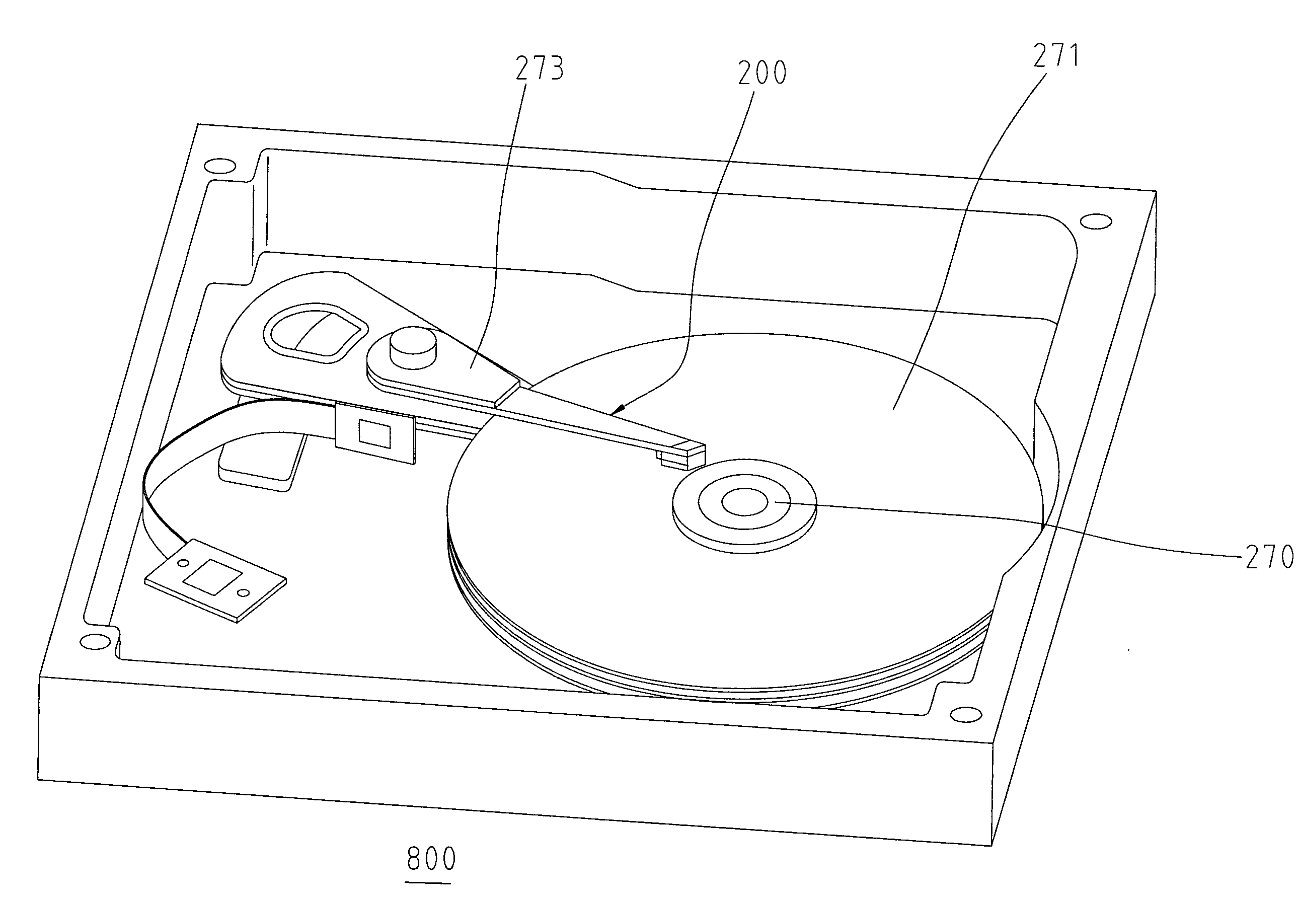
[0050]FIGS. 4a-5b denotes a HGA with weight-balanced slider according to a first embodiment of the invention. As shown in figures, the HGA 200 comprises a slider 203, a thin-film PZT micro-actuator 217 (as shown in FIG. 4d and FIG. 4e) to fine adjust displacement of the slider 203, and a suspension 290 to support both the slider 203 and...


PUM

PropertyMeasurementUnit
thicknessaaaaaaaaaa
weightaaaaaaaaaa
weight-balanceaaaaaaaaaa

Abstract

A HGA includes a load beam having a dimple formed thereon; a flexure including a suspension tongue and a support plate connected with the suspension tongue; and a slider having a leading edge and trailing edge opposite to the leading edge. The slider is mounted on the flexure such that the slider is supported by the dimple at the center of the slider. The leading edge is attached on the suspension tongue and trailing edge is attached on the support plate. A weight-balance structure is formed on the suspension tongue of the flexure to balance the weight of the HGA between a portion from the trailing edge to the slider center and another portion from the leading edge to the slider center. The invention also discloses various methods of manufacturing HGA with the balanced weight.

Description

FIELD OF THE INVENTION[0001]The present invention relates to information recording disk drive devices and, more particularly, relates to a head gimbal assembly (HGA) having balanced weight at leading edge portion and trailing edge portion of its slider, a disk drive unit with the same and manufacturing method thereof.BACKGROUND OF THE INVENTION[0002]One known type of information storage device is a disk drive device that uses magnetic media to store data and a movable read / write head that is positioned over the media to selectively read from or write to the disk.[0003]Consumers are constantly desiring greater storage capacity for such disk drive devices, as well as faster and more accurate reading and writing operations. Thus, disk drive manufacturers have continued to develop higher capacity disk drives by, for example, increasing the density of the information tracks on the disks by using a narrower track width and / or a narrower track pitch. However, each increase in track density...

Claims


Application Information

Patent Timeline
Patent Type & Authority Applications(United States)
IPC IPC(8): G11B5/48
CPCG11B5/4813
Inventor YAO, MINGGAOXIE, YIRU
Owner SAE MAGNETICS (HK) LTD
Why Eureka
Try Eureka