Radiant Gas Burner Unit

a burner unit and radiant gas technology, applied in the direction of gaseous heating fuel, combustion types, stoves or ranges, etc., can solve the problems of limiting the use of the burner unit to ovens and other applications of conventional size, which are of considerable bulk, and achieve the effect of improving heat distribution and reducing the size of the uni

Inactive Publication Date: 2009-02-05
SOLARFLO
View PDF69 Cites 15 Cited by
  • Summary
  • Abstract
  • Description
  • Claims
  • Application Information

AI Technical Summary

Benefits of technology

[0007]The burner unit disclosed here is an improved radiant burner that is very shallow in the direction perpendicular to the radiating surface, or a thin radiating burner unit. The decreased size of the unit is enabled by the use of multiple, smaller diameter, shorter mixing tubes, extending across the width of the burner unit, and receiving a fuel / air mixture from multiple gas sources along the side of the burner unit. Additionally, the burner unit of the present application has been shown though experimentation to provide improved heat distribution.

Problems solved by technology

This height dimension limits use of the burner units to ovens and other applications of conventional size, which are of considerable bulk.

Method used


Image

  • Radiant Gas Burner Unit
  • Radiant Gas Burner Unit
  • Radiant Gas Burner Unit

Examples


Embodiment Construction

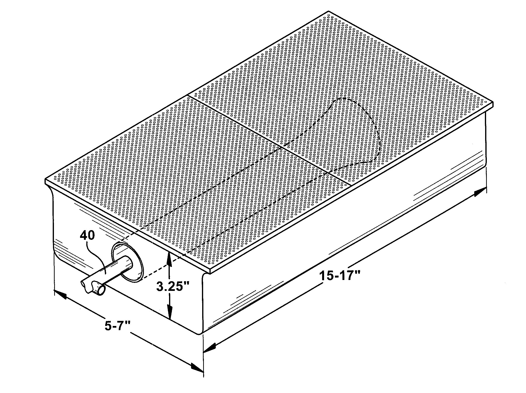
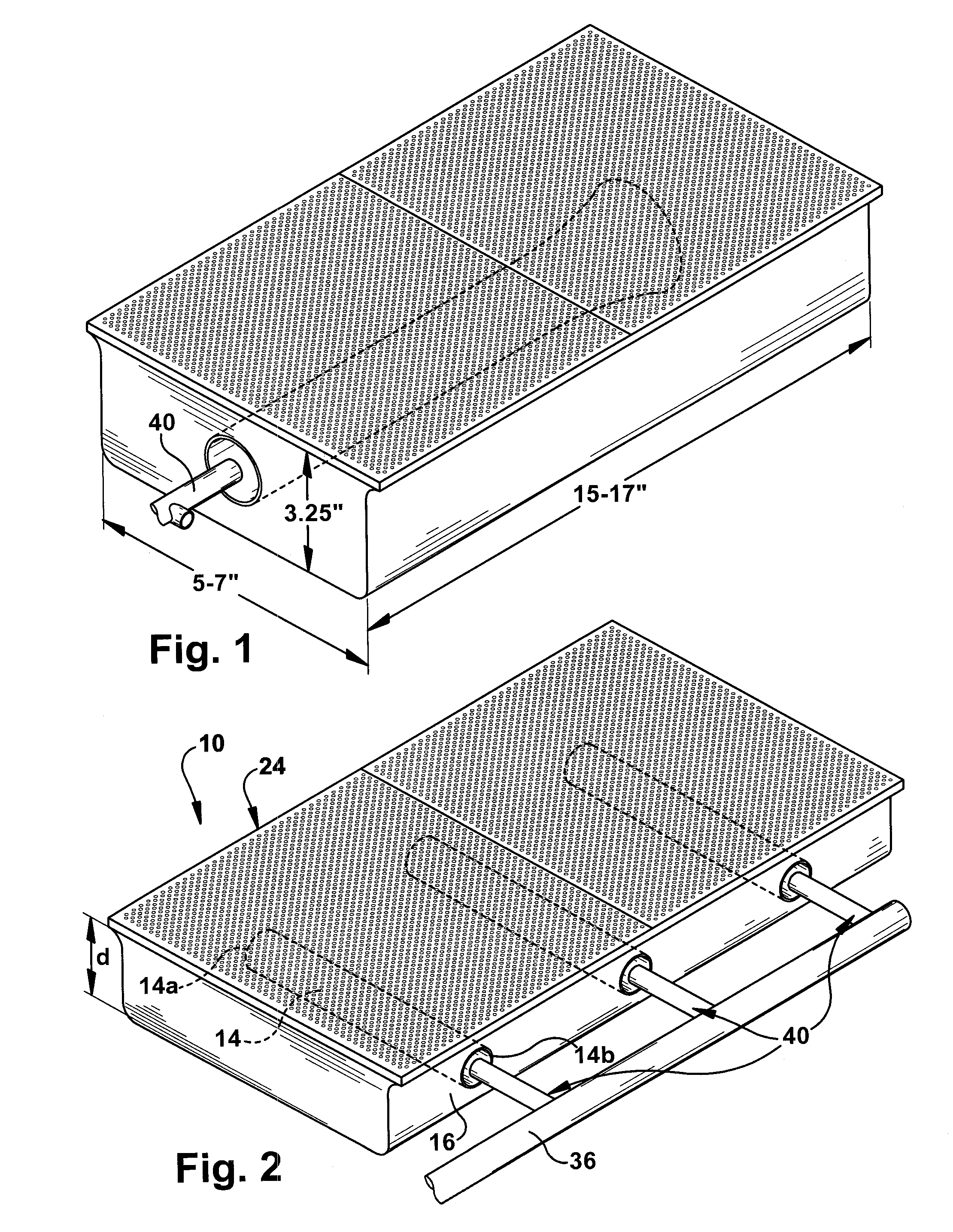
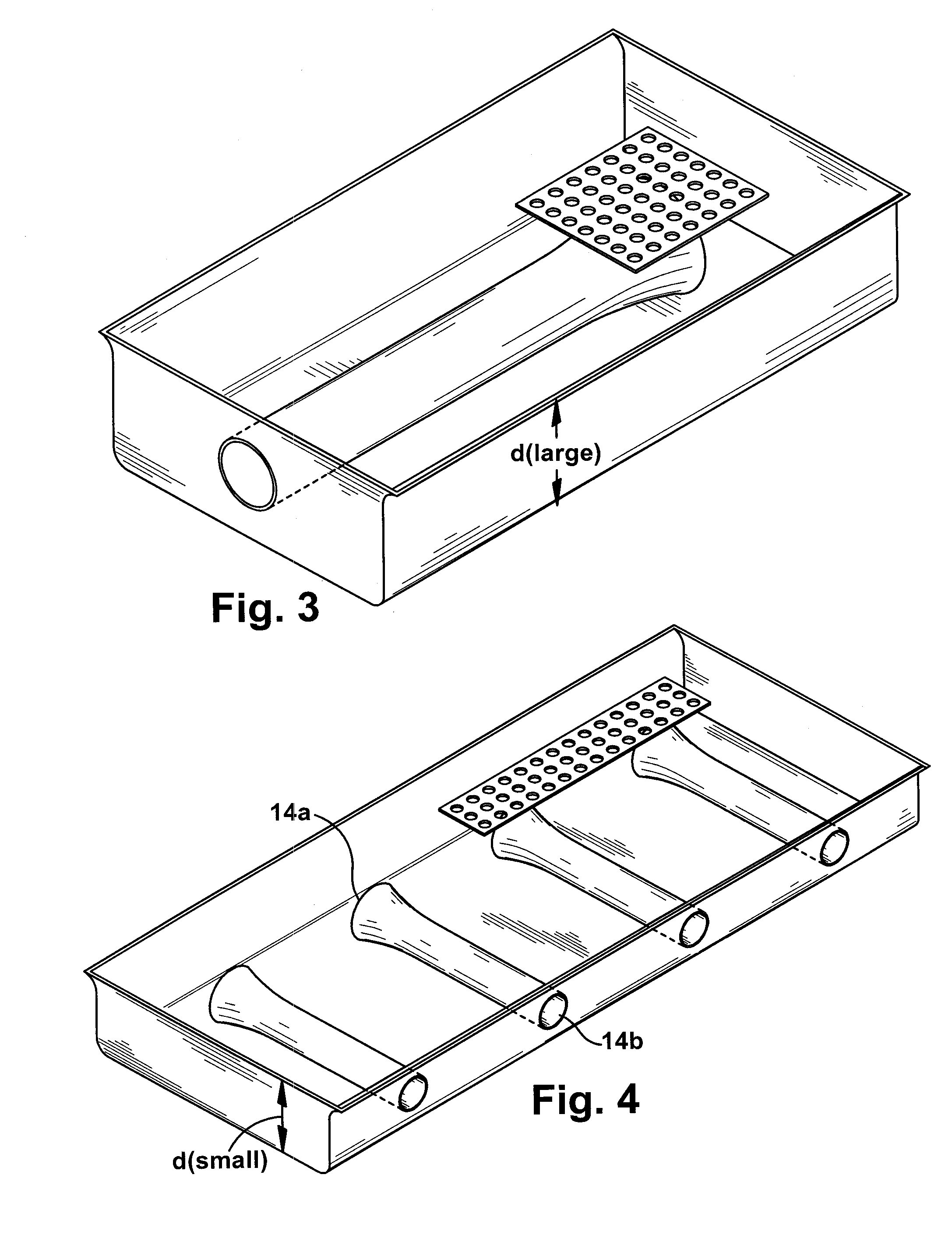
[0018]The present application provides an improved radiant gas burner unit 10. General and partial views of the present unit 10 are shown in FIGS. 2 and 4-7, while a prior art radiant gas burner unit is depicted in FIGS. 1 and 3. The present improved unit 10 includes a shallow box or base 12 having two long side walls and two shorter side walls. As shown in FIGS. 5 and 6, the box 12 includes first and second halves 12b and12a, respectively. The first half 12b of the shallow box 12 supports multiple mixing tubes 14. At least three mixing tubes 14 are provided within the first half 12b of the shallow box 12, and extend through spaced openings 15 formed in one long side wall 16 of the shallow box 12, as shown in FIG. 5. Alternatively, the inlet end 14b of the mixing tubes 14 may end flush with the side wall 16 of the shallow box, as shown in FIG. 2. In either embodiment, a sufficient gap 38 is provided between the air / gas inlet end 14b of the mixing tube 14 and a gas manifold or gas su...


PUM


Abstract

An improved radiant gas burner unit is provided having a shallow base with long walls and shorter walls. The shallow base supports a radiant gas burner plate or plates having openings therethrough, and forming an external surface of the base for emitting high temperature gas radiation. At least three mixing tubes are provided aligned with the shorter wall, and having two open ends. The first open end is positioned within the base and the second open end is positioned adjacent corresponding openings formed through the long wall of the base. A gas supply line extends along the long wall and has gas outlets for ejecting gas across an open air gap positioned intermediate the gas outlet and the second open end of the mixing tubes. The ejected gas is mixed with air as it crosses the air gap, and is provided to the openings of the radiant gas burner plate for combustion which produces high temperature radiation on the radiant gas burner plate and external surface of the base.

Description

FIELD OF INVENTION[0001]The present application is directed to an improved radiant gas burner unit, and more particularly to a shallow radiant gas burner unit with side gas inlets and improved heat distribution.BACKGROUND[0002]The use of radiant burners is common in connection with conventional cooking and heating systems. The radiating surface of the burner is typically a ceramic plate with densely spaced holes through which a combustible mixture of gas and air flows. The air / gas mixture is ignited at the ceramic surface and combustion takes place at the surface as well as partially in the holes. The velocity of the air / gas mixture through the holes is no less than the backward flame propagation velocity, so that the flame does not travel into the plenum behind the ceramic plate.[0003]Past systems of the type disclosed, for example, in U.S. Pat. No. 6,012,444 provide a radiant burner which is approximately 28 inches by 12 inches. Such units disperse the air / gas mixture within a cha...

Claims


Application Information

Patent Timeline
Patent Type & Authority Applications(United States)
IPC IPC(8): F24C3/04F23D14/12
CPCF23D14/14F23D2203/104F24C3/04F23D2212/10F23D14/145
Inventor VON HERRMANN, PIETER J.FREDERICK, DAVID
Owner SOLARFLO
Why Eureka
Try Eureka