Brake Structure for a Main Shaft of a Direct Drive Torque Motor

Inactive Publication Date: 2009-02-05
HIWIN MIKROSYST
View PDF5 Cites 7 Cited by
  • Summary
  • Abstract
  • Description
  • Claims
  • Application Information

AI Technical Summary

Benefits of technology

[0009]The primary objective of the present invention is to provide a brake structure for a main

Problems solved by technology

Firstly, the conventional direct drive torque motor utilizes the power of the torque motor to stop the main shaft.
The main shaft still cannot stop immediately since it still has rotation inertia force when the torque motor is stopped, it is hard to control when applying to the products of angle controlling, rotating speed

Method used


Image

  • Brake Structure for a Main Shaft of a Direct Drive Torque Motor
  • Brake Structure for a Main Shaft of a Direct Drive Torque Motor
  • Brake Structure for a Main Shaft of a Direct Drive Torque Motor

Examples


Example

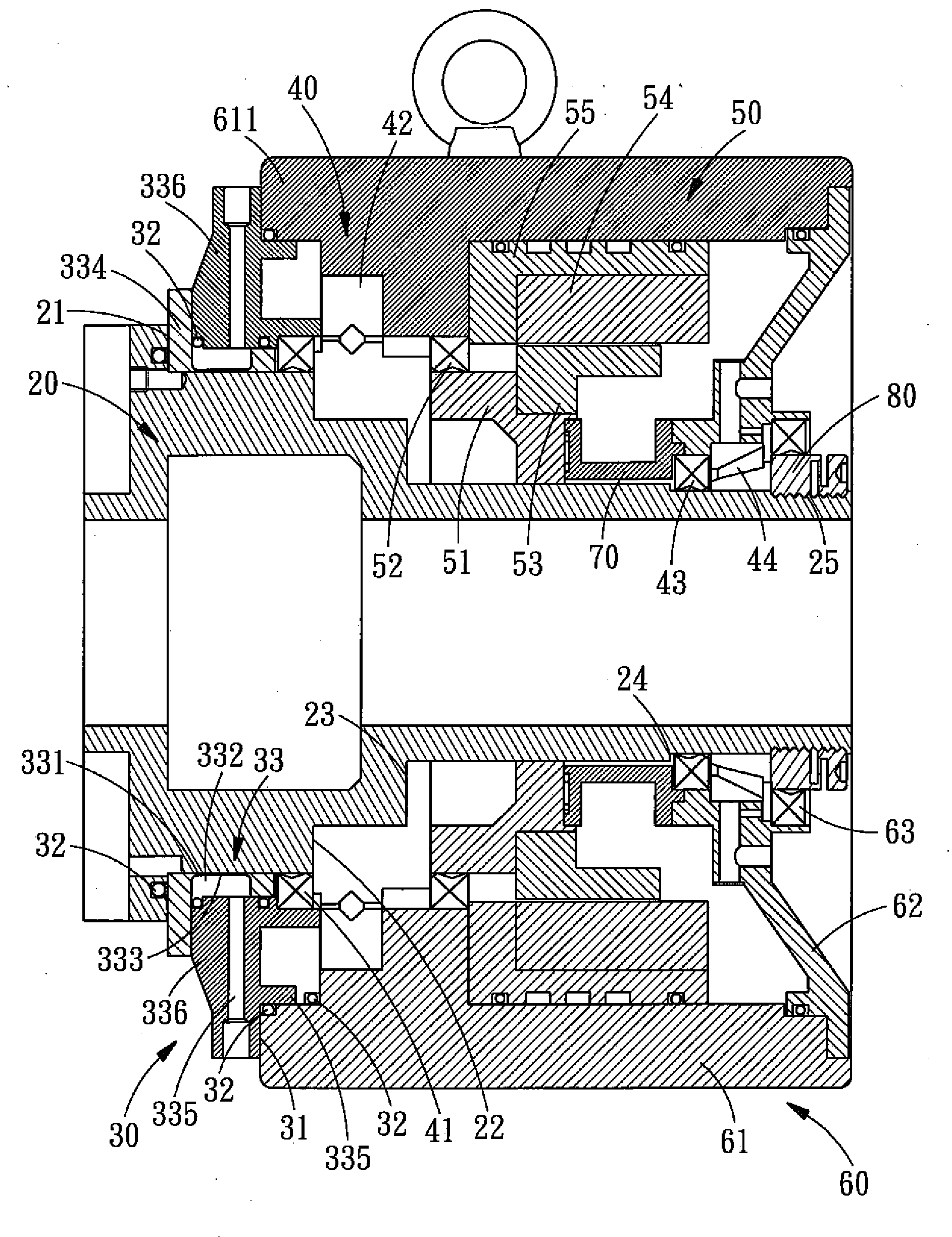
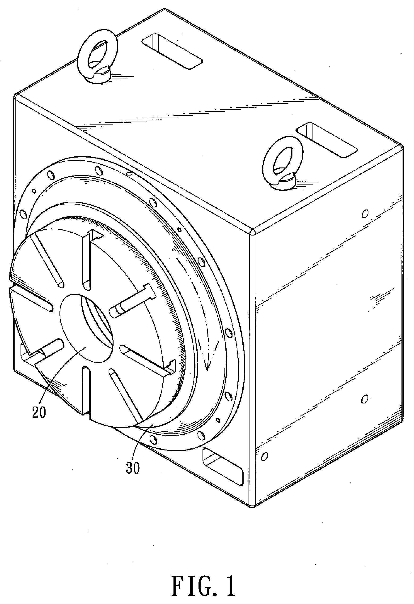
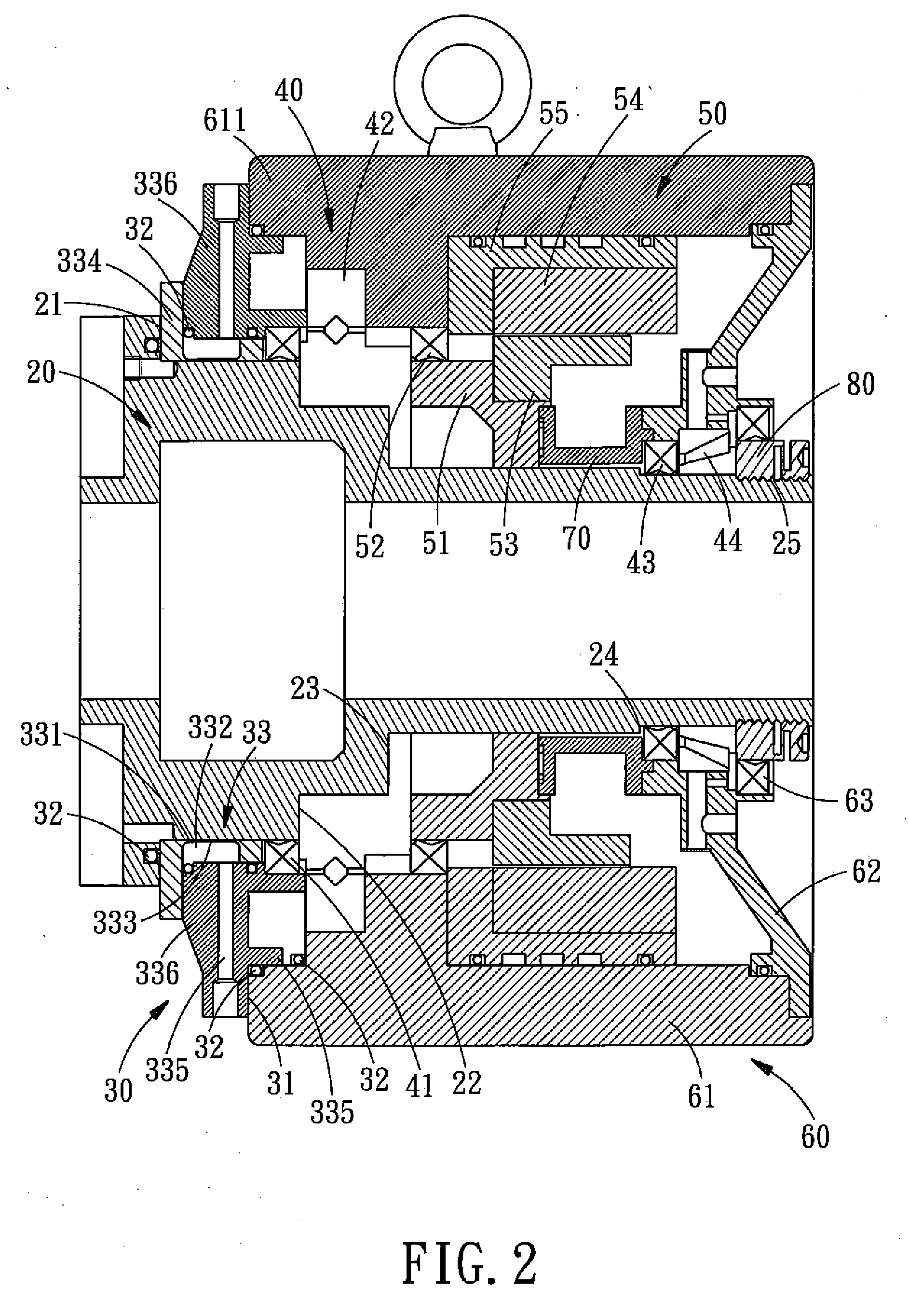
[0022]Referring to FIGS. 1-3, a brake structure for a main shaft of a direct drive torque motor in accordance with the present invention comprises a main shaft 20, a brake assembly 30, a bearing assembly 40, a direct drive torque motor 50, a body 60, a position-sensing member 70 and an adjustment nut 80.

[0023]A first stage 21, a second stage 22, a third stage 23, a fourth stage 24, and an outer thread portion 25 are orderly tapered from one end to the other end of an outer surface of the main shaft 20, and the outer thread portion 25 is located at one end of the main shaft 20.

[0024]The brake assembly 30 includes a brake seat subassembly 33 and a plurality of O-shaped rings 32. The brake seat subassembly 33 includes a L-shaped seat 334 and a cover 336. An annular brake oil room 332 is formed between the L-shaped seat 334 and the cover 336 and sealed by the O-shaped ring 32. In a center of the brake seat subassembly 33 is defined a hole 331 for insertion of the main shaft 20, an inner...


PUM


Abstract

A brake structure for a main shaft of a direct drive torque motor comprises a body, a direct drive torque motor, a main shaft and a brake assembly. The main shaft is provided for fixing the torque motor and the body, and the brake assembly is mounted between the body and the main shaft. An annular brake oil room of the brake assembly is positioned against the main shaft, and the brake seat subassembly has a thinner brake deformation wall formed between the annular brake oil room and the main shaft. The annular brake oil room utilizes its high pressure caused deformation to the brake deformation wall, thus achieving a braking effect by pressing the main shaft. Thereby, the present invention is easy to assemble, and not only can stop the main shaft quickly, but also has a greater locking force.

Description

BACKGROUND OF THE INVENTION[0001]1. Field of the Invention[0002]The present invention relates to a brake structure for a main shaft of a direct drive torque motor, and more particularly to a brake structure for a main shaft of a direct drive torque motor which is easy to assemble and not only can stop the main shaft quickly, but also has a greater locking force.[0003]2. Description of the Prior Art[0004]Nowadays, motor device is used more and more widely in the field of industry, which mainly includes the types of outer rotor, inner rotor and so on. In addition to the effect of high precision, the motor device also has low friction loss, high energy conversion efficiency and low noise. Therefore, the motor device is very important in terms of various machines.[0005]Currently, direct drive torque motor is applied to the drive of the axis equipments: such as the automatic equipment, the indexing plate and different kinds of tool machines. A main shaft of a conventional direct drive to...

Claims


Application Information

Patent Timeline
IPC IPC(8): F16D67/04
CPCF16D65/14F16D2125/14F16D2121/02
Inventor CHENG, FU-YUANCHAO, CHIH-HSIEN
Owner HIWIN MIKROSYST
Why Eureka
Try Eureka