Movable contact point

a technology of contact point and movable plate, which is applied in the direction of contact, contact surface shape/structure, snap-action arrangement, etc., can solve the problems of reducing the productivity of processing and producing movable contact points, and achieves the effects of improving the durability of punching, reducing the frequency of replacing, and increasing the thickness

Inactive Publication Date: 2009-02-05
PANASONIC CORP
View PDF6 Cites 2 Cited by
  • Summary
  • Abstract
  • Description
  • Claims
  • Application Information

AI Technical Summary

Benefits of technology

[0016]A movable contact point according to the present invention is a movable contact point including a dome-shaped portion which is made of an elastic metal thin plate and protruded upwardly at its center portion, and further including at least three protrusions formed, on the dome-shaped portion, to protrude downwardly at positions which are evenly spaced apart from the center position of the dome-shaped portion, wherein the protrusions are formed to have a quadrangular-pyramid shape protruding downwardly and having a spherical-shaped apex portion. With the movable contact point according to the present invention, it is possible to ensure stable contact at three or more points in operation and, also, it is possible to employ a punch with a quadrangular-pyramid-shaped tip end portion for processing and forming the protrusions. This can cause the punch to have a larger thickness at its tip end portion, thereby improving the durability of the punch and reducing the replacing frequency. Furthermore, the joint portion between the dome-shaped portion and the protrusions on the movable contact point can be formed to have a moderate curved surface, thereby alleviating the concentration of stresses at the joint portion. Further, it is possible to ensure the height of the protrusions on the movable contact point more easily and stably than in cases of conventional semispherical-shaped protrusions, thereby ensuring a contact state with higher stability.

Problems solved by technology

Accordingly, in order to form movable contact points 1 using such a punch with a tip end with a small diameter, there is a need for replacing the punch with a higher frequency since the punch having the tip end with the small diameter has poor durability, which has induced the problem of reduction of the productivity in processing and producing movable contact points 1.

Method used


Image

  • Movable contact point
  • Movable contact point
  • Movable contact point

Examples


first embodiment

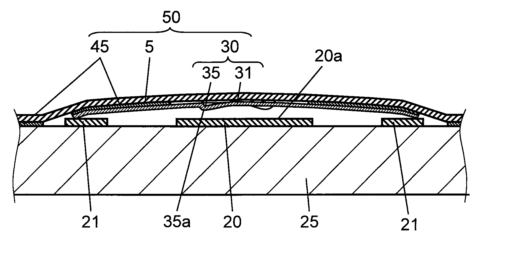
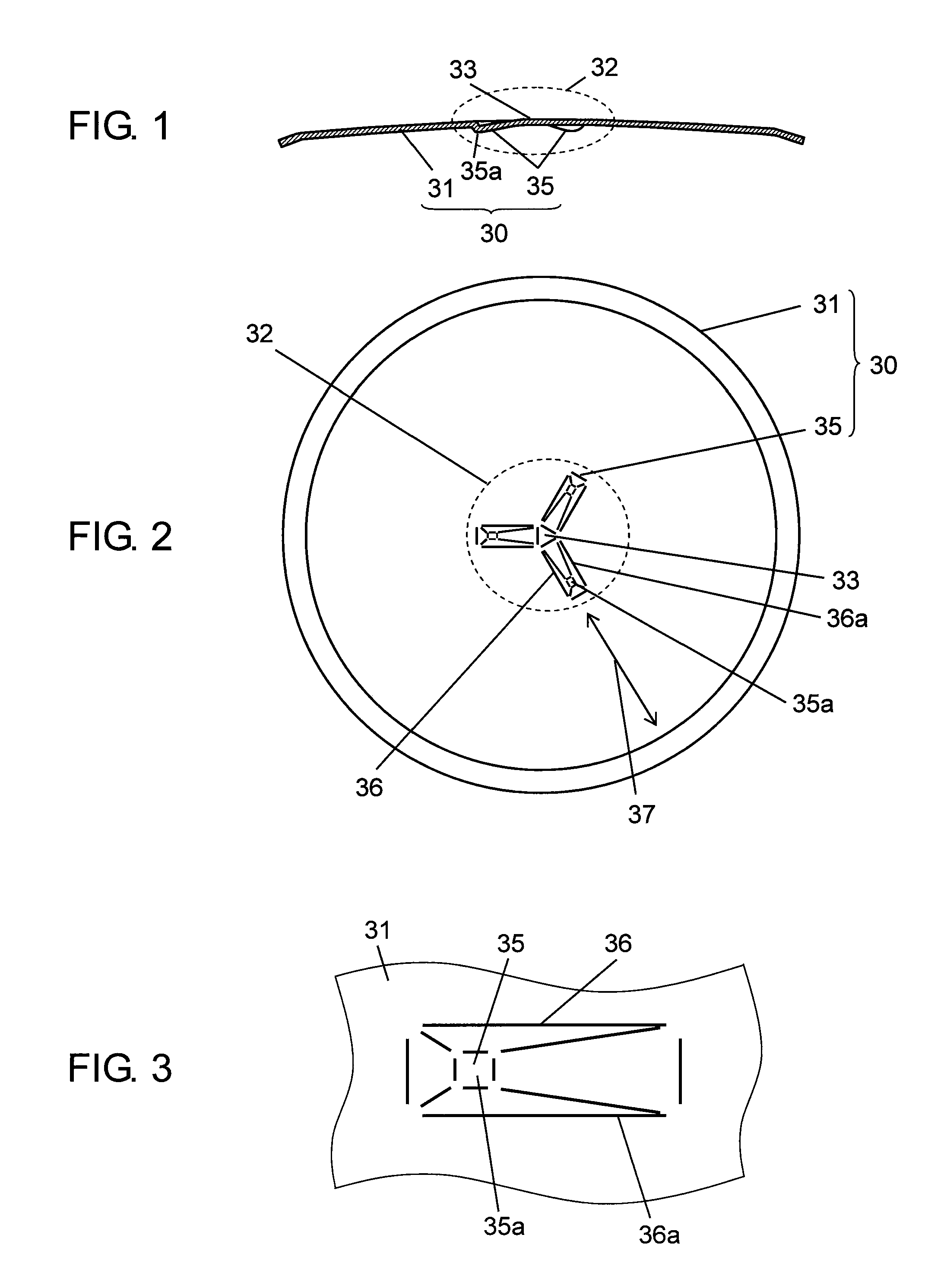
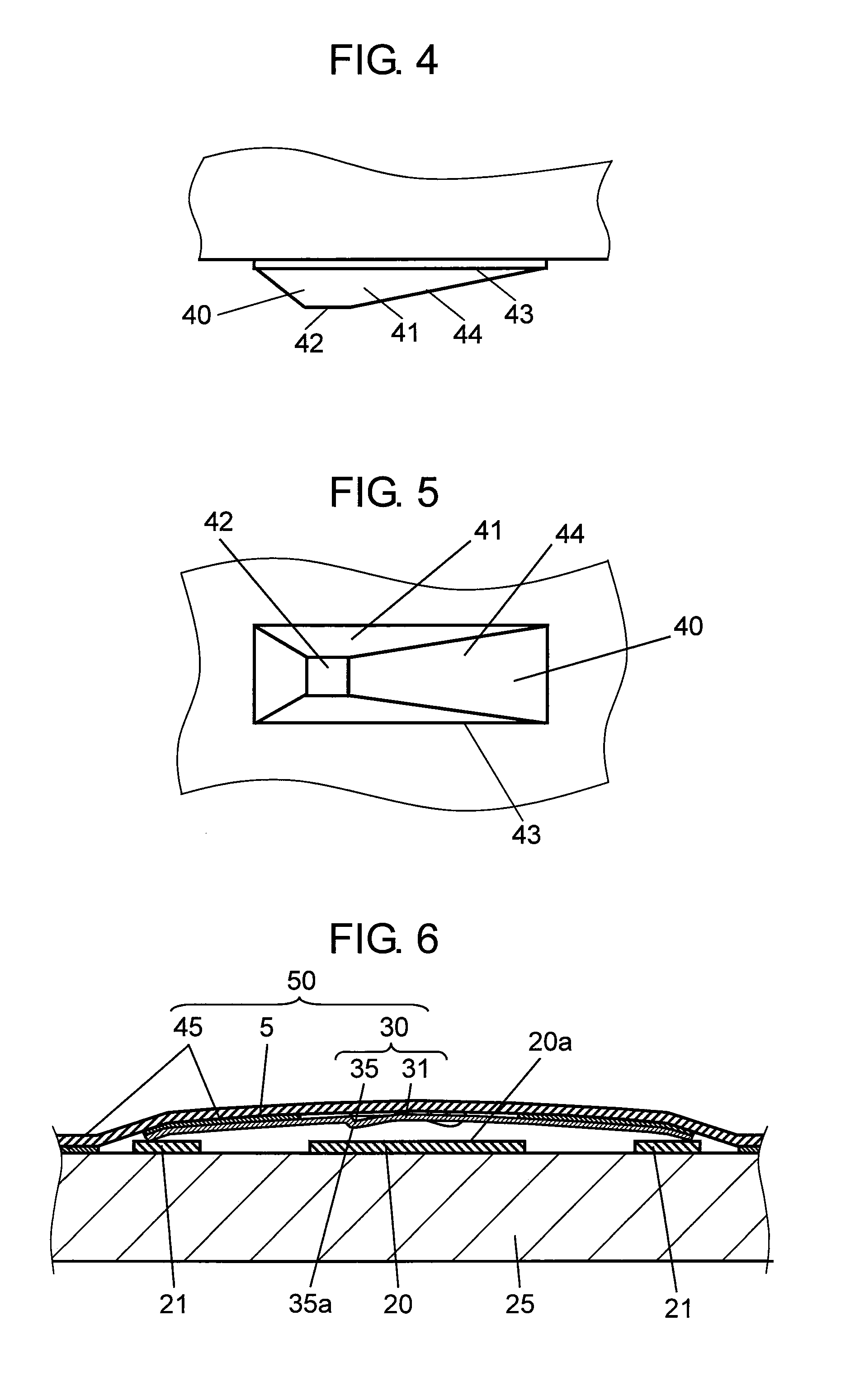
[0026]FIG. 1 is a cross-sectional view of a movable contact point according to the first embodiment of the present invention. FIG. 2 is a bottom view of the same movable contact point. FIG. 3 is an enlarged plan view illustrating a protrusion which is a main part of the same movable contact point, at the lower surface of the protrusion. FIG. 4 is a side view of a punch for use in forming the same movable contact point. FIG. 5 is a bottom view of the same punch.

[0027]In FIG. 1 and FIG. 2, movable contact point 30 is made of an elastic thin-plate metal and has dome-shaped portion 31 formed to have a dome-shaped contour which has a circular shape when viewed at its upper and lower surfaces and protrudes upwardly at its center portion. Further, at center position 32 of dome-shaped portion 31, there are formed downwardly-protruding protrusions 35 with a substantially-quadrangular-pyramid shape which are placed with a pitch of 120 degrees.

[0028]Three protrusions 35 are provided to have th...


PUM


Abstract

A movable contact point according to the present invention includes a dome-shaped portion protruded upwardly at its center portion and at least three protrusions formed, on the dome-shaped portion, to protrude downwardly at positions which are evenly spaced apart from the center position of the dome-shaped portion, wherein the protrusions are formed to have a quadrangular-pyramid shape protruding downwardly and having a spherical-shaped apex portion.

Description

BACKGROUND OF THE INVENTION[0001]1. Field of the Invention[0002]The present invention relates to a movable contact point for use in forming a push-type switch usable in various types of electronic apparatuses, such as cellular phones.[0003]2. Description of the Related Art[0004]In recent years, there has been significantly advanced reduction of the sizes and the thicknesses of electronic apparatuses, such as movable communication apparatuses including cellular phones. Particularly, push-type switches having thin-shaped structures have been desirably used in the operation portions of such electronic apparatuses. Further, in forming such push-type switches, so-called movable contact point members structured to include movable contact points held on sheet members have been employed in many cases and, also, there has been a need for maintaining preferable touch feeling and long lives of such movable contact point members.[0005]Hereinafter, there will be described a switch structured to ...

Claims


Application Information

Patent Timeline
Patent Type & Authority Applications(United States)
IPC IPC(8): H01H13/00
CPCH01H11/04H01H2229/05H01H2205/016H01H13/48
Inventor SANO, YOSHIRO
Owner PANASONIC CORP
Why Eureka
Try Eureka