Multi-focal intraocular lens system and methods

a multi-focal, intraocular lens technology, applied in the field of multi-focal intraocular lens, can solve the problems of affecting the performance of accomodative iols, and affecting the accuracy of ambient brightness levels

Inactive Publication Date: 2009-02-05
EA3TECH LLC
View PDF7 Cites 24 Cited by
  • Summary
  • Abstract
  • Description
  • Claims
  • Application Information

AI Technical Summary

Benefits of technology

[0017]In one embodiment, the innovative photosensor measures and determines both the light intensity and distribution traversing the pupil, and the change in light intensity received at individual sensor elements. By measuring the light distribution, and change in light distribution, on the photosensor array, the size of pupil is determined. By measuring the temporal change in light intensity of illuminated sensor elements, any changes in the ambient brightness is also determined. In this embodiment, the changes in pupil size due to both the brightness reflex and the near synkinesis reflex can be determined, and the photosensor and range-finding apparatus can distinguish between both changing light conditions and changes to the distance to the object of regard. As discussed below, the ability to detect changes in relative light levels can be used to distinguish between pupil reflex responses due to both brightness and synkinesis causes and can thereby accurately determine changes in ambient brightness levels as well as the distance to an object of regard.

Problems solved by technology

For example, as a person ages, the natural crystalline lens of the eye loses plasticity and it becomes increasingly difficult to deform the stiffening lens to achieve accommodation sufficient to focus on objects at different nearby distances.
Unfortunately, these types of accommodative IOLs are substantially inferior in performance when compared to a healthy natural crystalline lens, and fail to have the capability to accurately and reliably focus on demand.
The ciliary body is known to be very fragile and difficult to work with, however, making these solutions relatively complex and unappealing.
A significant problem with this approach, however, is that often there are multiple objects in the line of vision, making it difficult or unable to distinguish between the desired object of regard and an intervening object (e.g., raindrops).

Method used


Image

  • Multi-focal intraocular lens system and methods
  • Multi-focal intraocular lens system and methods
  • Multi-focal intraocular lens system and methods

Examples


Embodiment Construction

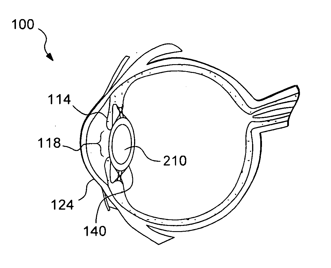
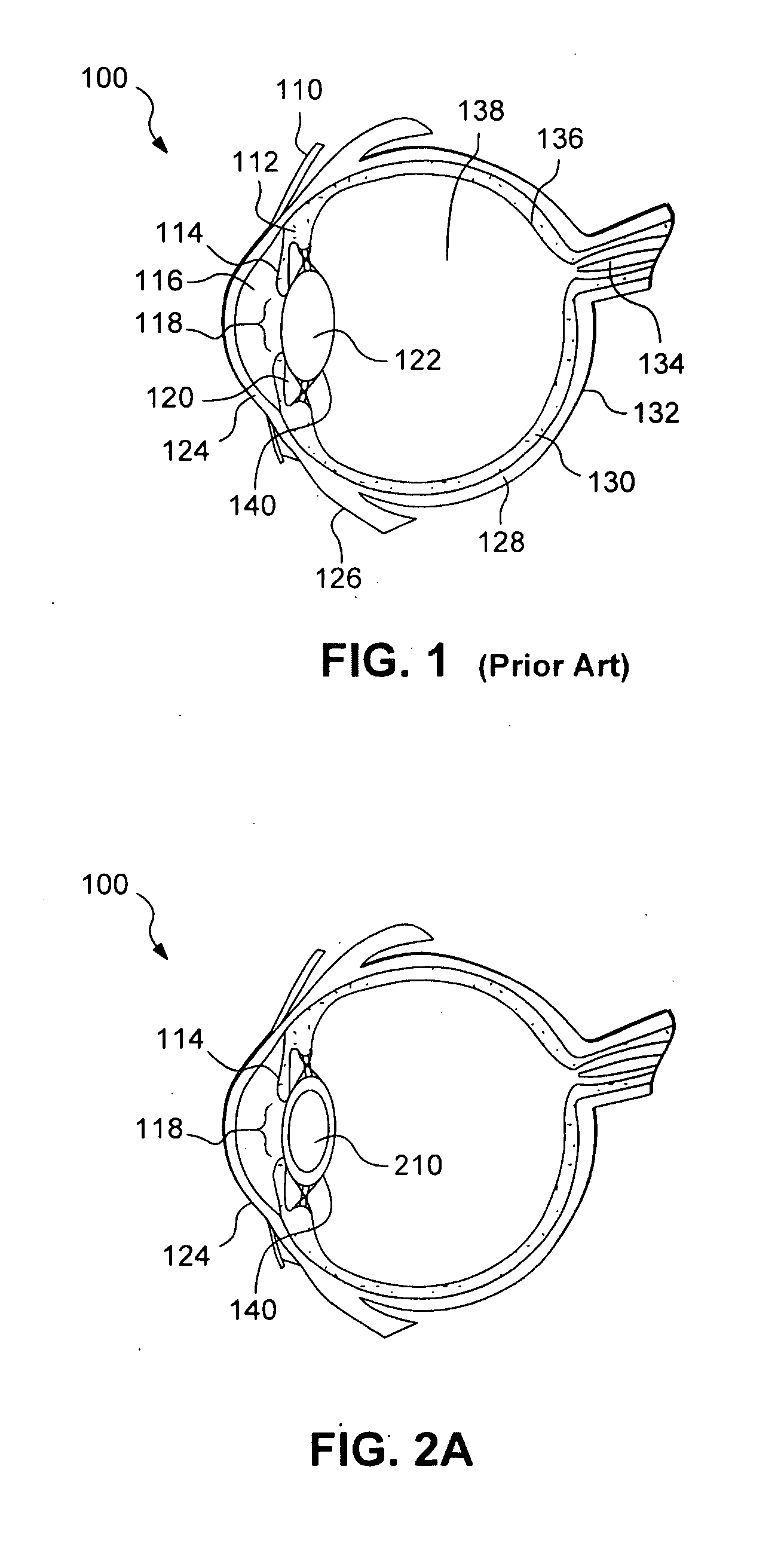
[0039]FIG. 1 shows the anatomical structure of the eye 100 with labels, including: conjunctiva 110; ciliary body 112; iris 114; pupil 118; anterior chamber 116 (containing aqueous humour); crystalline lens 122; cornea 124; extraocular muscle 126; scelera 128; choroid 130; macula 132; optic nerve 134; retina 136; vitreous humor 138; and capsular bag 140. The crystalline lens 122 is encapsulated by a capsular bag 140. During a typical lens replacement surgery, the natural lens 122 is removed from the capsular bag 140, and the new IOL is implanted inside the capsular bag 140 by well known surgical techniques. The IOL can be inserted in a folded condition and then unfolded once inside the capsular bag 140.

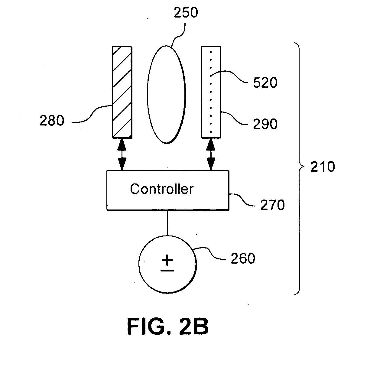
[0040]FIG. 2A shows an example of a multi-focal IOL system 210 implanted inside the capsular bag 140. FIG. 2B illustrates a blow up of the IOL system 210 shown in FIG. 2A. Referring to FIG. 2B, in one embodiment, the implanted IOL system 210 includes an electroactive lens 250 having el...


PUM


Abstract

The invention pertains to methods, components, and operations of multi-focal intraocular lens systems, including range finding for driving same and for discriminating between multiple objects and varying brightness conditions. The invention also pertains to intraocular photosensors and range-finding methods to be used with intra-ocular lens systems, and components, that provide multi-focal IOL capabilities in dynamic visual environments.

Description

CROSS REFERENCE TO RELATED APPLICATION [0001]This application claims priority to and benefit of, U.S. Provisional Patent Application Ser. No. 60 / 953,640, filed Aug. 2, 2007, the contents of which are incorporated herein by reference.FIELD OF INVENTION [0002]Example aspects of the present invention generally relate to multi-focal intraocular lens (“IOL”) systems, and more particularly to intraocular photosensors and range-finding methods to be used with IOL systems and components that provide multi-focal IOL capabilities in dynamic visual environments.DESCRIPTION OF THE RELATED ART[0003]In the human visual system, in order to selectively focus on nearby objects such as those less than 20 feet away, the focal length of an eye's lens must change. In a normal eye, this is achieved through the contraction of a ciliary muscle that is mechanically coupled to the lens. The extent of contraction of the ciliary muscle deforms the lens thereby changing the focal length, or power, of the lens. ...

Claims


Application Information

Patent Timeline
Patent Type & Authority Applications(United States)
IPC IPC(8): G02B7/04
CPCA61F2/1618A61F2/1624A61B3/10A61B3/112A61F2/14A61B5/6821
Inventor HOLLADAY, JACK T.
Owner EA3TECH LLC
Why Eureka
Try Eureka