Liquid Crystal Display Device

a liquid crystal display and display device technology, applied in non-linear optics, instruments, optics, etc., can solve the problems that the above-mentioned conventional static-electricity prevention structure is not applicable to the liquid crystal display device, and achieve the effects of convenient assembling operation, enhanced narrowing of the picture frame, and reliable electrical connection

Active Publication Date: 2009-02-05
PANASONIC LIQUID CRYSTAL DISPLAY CO LTD +1
View PDF0 Cites 41 Cited by
  • Summary
  • Abstract
  • Description
  • Claims
  • Application Information

AI Technical Summary

Benefits of technology

[0026]According to the present invention, due to the acquisition of conduction between the side wall of the metal-made backlight lower frame and the liquid crystal panel, narrowing of a picture frame can be enhanced. Further, with the use of the flexible conductive material (for example, conductive rubber cushion), a conductive path can be installed through a narrow space having many bent portions and hence, the reliable electrical connection between the liquid crystal panel and the ground member can be realized.

Problems solved by technology

However, the above-mentioned conventional static-electricity prevention structure is

Method used


Image

  • Liquid Crystal Display Device
  • Liquid Crystal Display Device
  • Liquid Crystal Display Device

Examples


embodiment 1

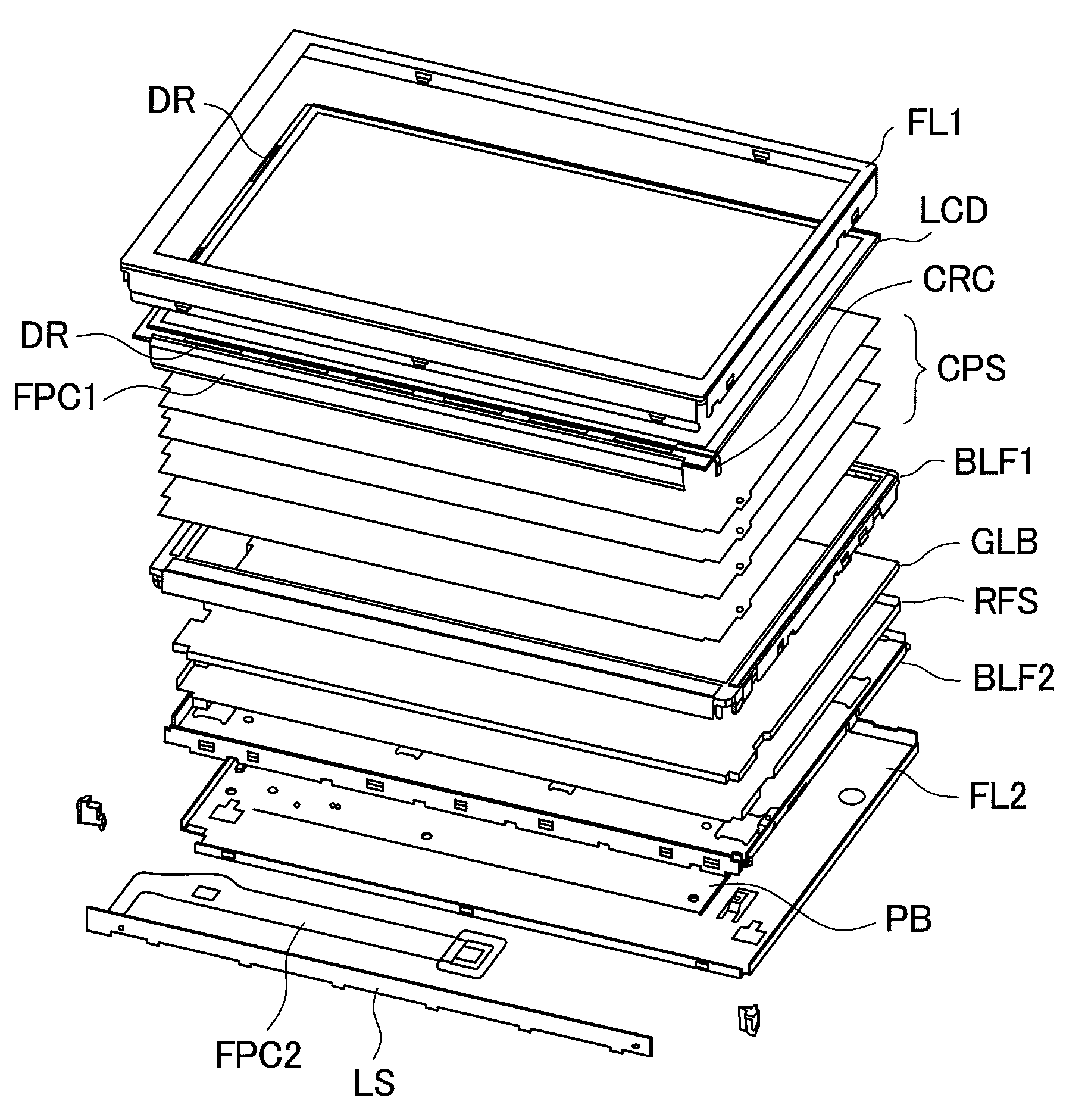
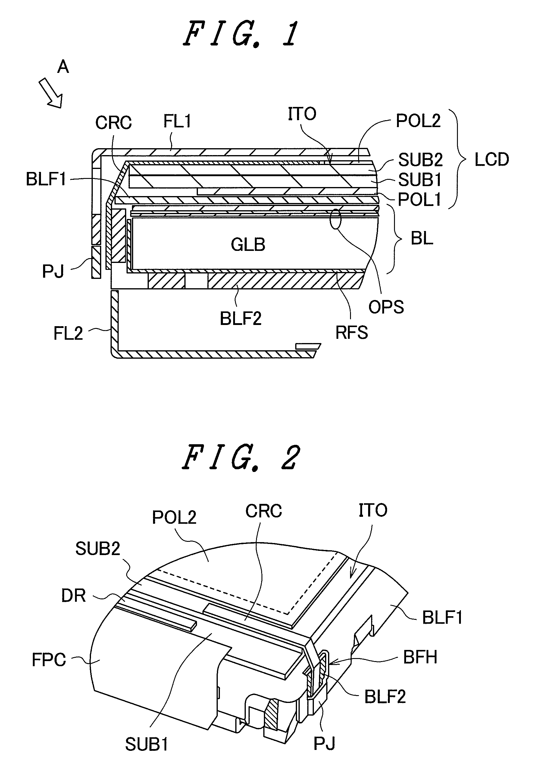
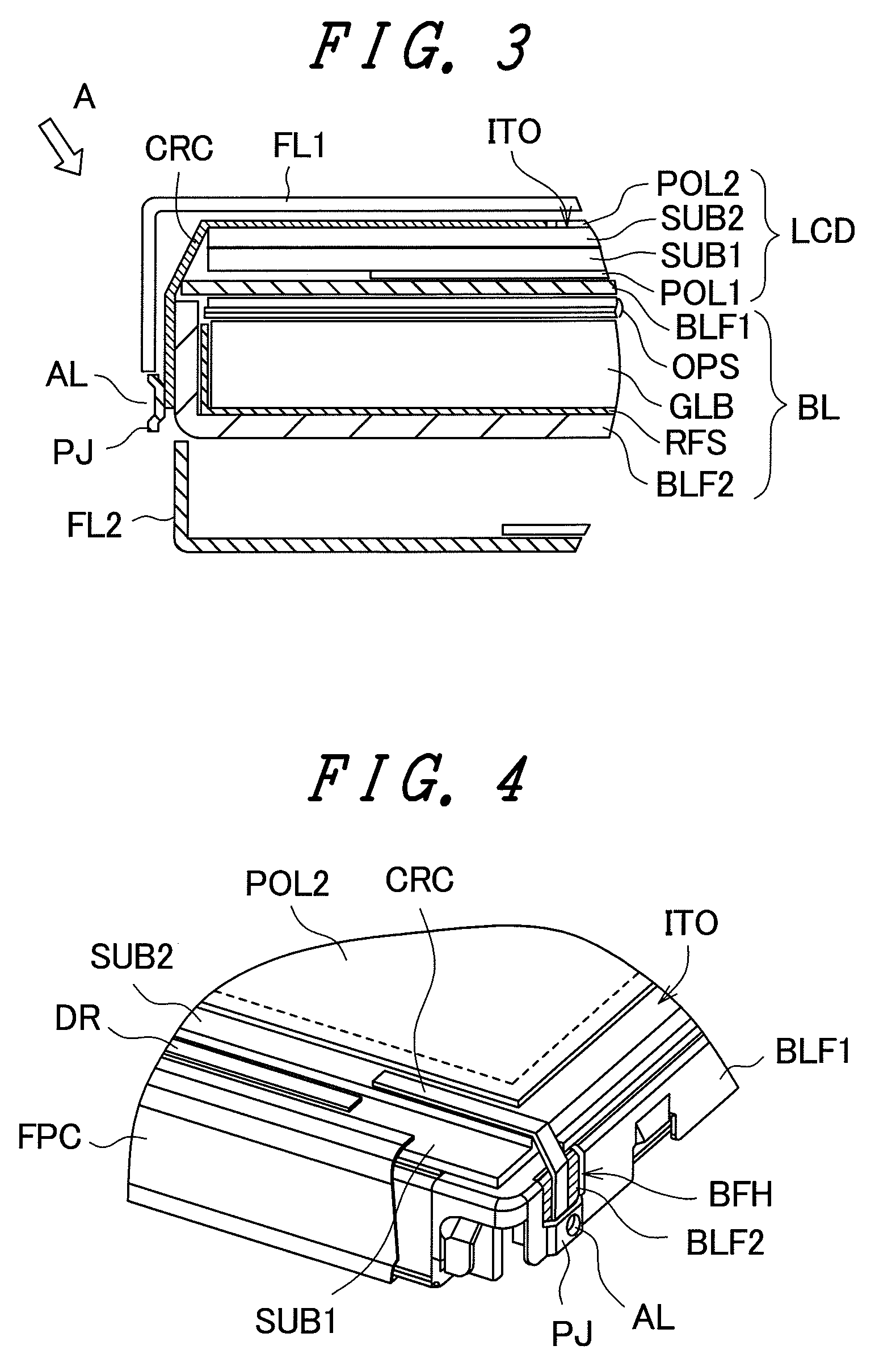
[0044]FIG. 1 is a cross-sectional view of an essential part for explaining an embodiment 1 of a liquid crystal display device of the present invention. Further, FIG. 2 is a perspective view of the essential part for explaining the embodiment 1 of the liquid crystal display device of the present invention as viewed in the direction indicated by an arrow A in FIG. 1. In FIG. 2, a technical feature of the embodiment 1 is exposed by removing an upper frame shown in FIG. 1. The liquid crystal display device includes a liquid crystal panel LCD and a backlight assembly BL. The liquid crystal panel LCD is constituted of a first substrate SUB1, a second substrate SUB2 and liquid crystal sandwiched between respective main surfaces of the first and second substrates SUB1, SUB2. On the main surface of the first substrate (being referred to as a TFT substrate hereinafter), pixel electrodes and active elements such as thin film transistors (TFT) are formed, and an image display is controlled by t...

embodiment 2

[0056]FIG. 5 is a perspective view of an essential part for explaining the embodiment 2 of the liquid crystal display device according to the present invention. In the embodiment 2, one side of the bulging portion PJ (one side of the bulging portion PJ in the longitudinal direction of the conductive rubber cushion CRC) in the embodiment 1 is separated from the backlight lower frame BLF2. The constitution of other parts of this embodiment is substantially equal to the constitution of the corresponding parts of the embodiment land hence, their repeated explanations are omitted. Due to such a constitution, it is possible to easily insert the conductive rubber cushion CRC between the backlight upper frame BLF1 and the backlight lower frame BLF2.

[0057]FIG. 6 is a cross-sectional view of an essential part for explaining the embodiment 2 of the liquid crystal display device according to the present invention. Further, FIG. 7 is a perspective view of the essential part for explaining the em...

embodiment 3

[0061]FIG. 8 is a cross-sectional view of an essential part for explaining the embodiment 3 of the liquid crystal display device according to the present invention. FIG. 9 is a perspective view of the essential part for explaining the embodiment 3 of the liquid crystal display device according to the present invention as viewed in the direction indicated by an arrow A in FIG. 8. Further, FIG. 10 is a developed view of the essential part of the liquid crystal display device. In these drawings, parts identical with the parts of the embodiment 1 are given same symbols.

[0062]In this embodiment, a bulging portion is not formed on a backlight upper frame, while a hole BFH which exposes a backlight lower frame to the outside is formed in the backlight upper frame.

[0063]On the other hand, a recessed portion REC is formed on a backlight lower frame BLF2.

[0064]A conductive rubber cushion CRC which extends toward a side wall of the backlight lower frame BLF2 is connected to the recessed portio...


PUM


Abstract

The present invention provides a liquid crystal display device in which a light transmitting conductive layer formed on a surface of a color filter substrate is electrically connected with a backlight lower frame using conductive rubber. One end of the conductive rubber is connected with the light transmitting conductive layer, and another end of the conductive rubber is connected with the backlight lower frame through a hole which is formed in a backlight upper frame. The liquid crystal display device of the present invention can remove static electricity charged in a surface of a display panel and, at the same time, can realize the narrowing of a picture frame and the reduction of thickness thereof.

Description

CROSS-REFERENCE TO RELATED APPLICATION[0001]The present application claims priority from Japanese application JP2007-199688 filed on Jul. 31, 2007, the content of which is hereby incorporated by reference into this application.BACKGROUND OF THE INVENTION[0002]1. Field of the Invention[0003]The present invention relates to a liquid crystal display device, and more particularly to a liquid crystal display device which is configured to surely discharge static electricity charged in a front surface side of a liquid crystal display panel to a ground member such as a metal frame.[0004]2. Related Art[0005]The liquid crystal display device is configured such that a backlight assembly, a display control circuit board and the like are combined to a liquid crystal panel and these parts are formed into an integral body using a frame. The liquid crystal panel is configured such that a first substrate, that is, a thin film transistor substrate (TFT substrate) which forms pixel circuits each const...

Claims


Application Information

Patent Timeline
IPC IPC(8): G02F1/1333
CPCG02F1/133308G02F2001/133334G02F1/134363G02F1/133334
Inventor FUKAYAMA, NORIHISAMAEHARA, MUTSUMI
Owner PANASONIC LIQUID CRYSTAL DISPLAY CO LTD
Why Eureka
Try Eureka