Liquid-Crystal Display Device
- Summary
- Abstract
- Description
- Claims
- Application Information
AI Technical Summary
Benefits of technology
Problems solved by technology
Method used
Image
Examples
first embodiment
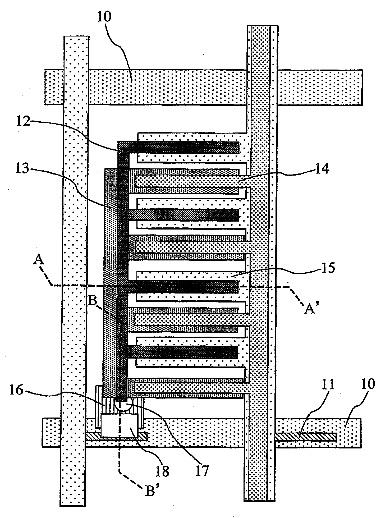
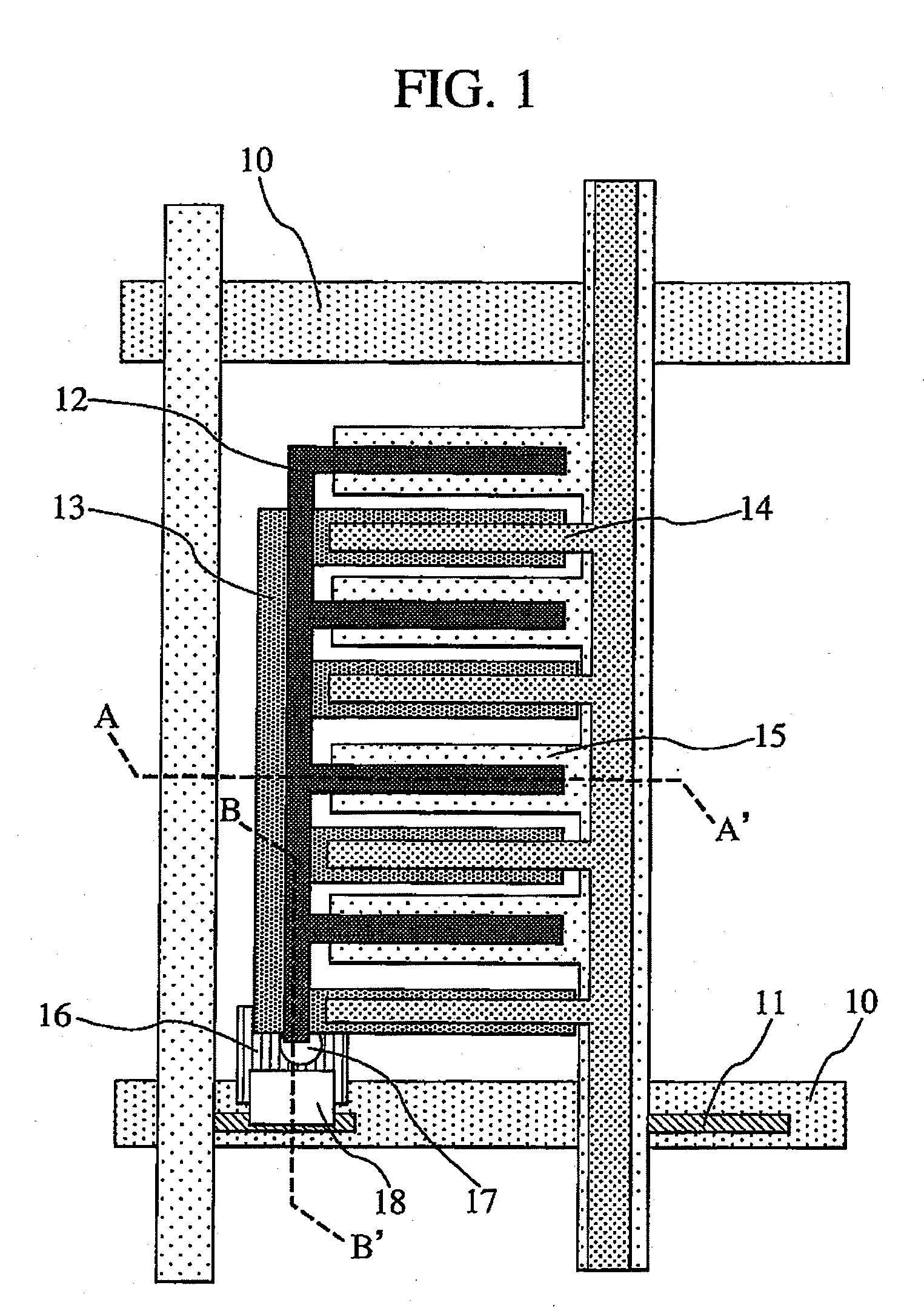
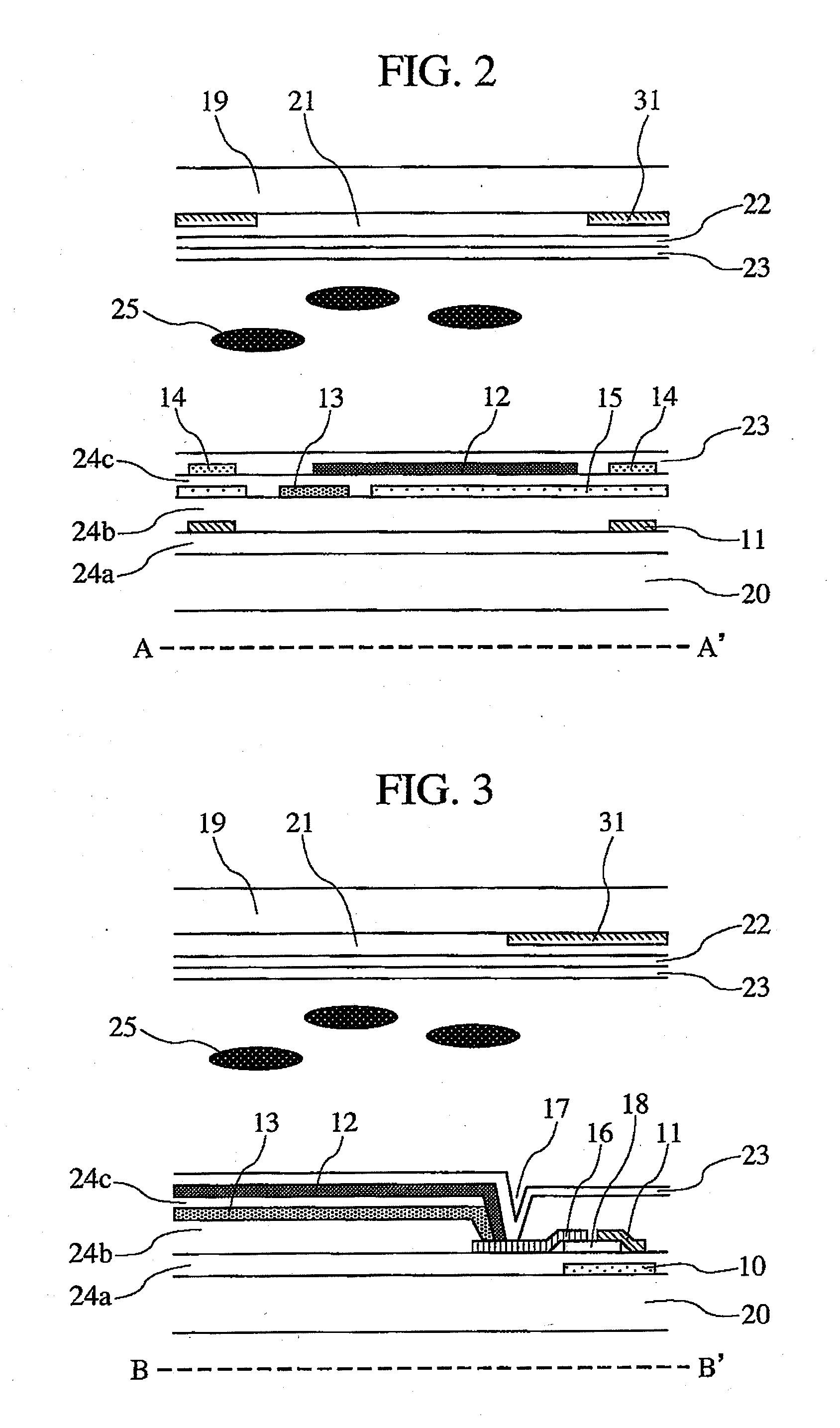
[0032]A first embodiment of the present invention is described below using FIGS. 1 to 11. The present embodiment is characterized in that in a liquid-crystal display device of an IPS mode that uses interdigital electrodes, the interdigital electrodes are arranged in twin-layer form via an interlayer insulator, in that the two electrode layers have either a common potential or a source potential, in that the electrode layer having either potential and the other electrode layer having the other potential are arranged to overlap each other vertically via the interlayer insulator, in that of the two overlapping electrodes, the electrode disposed at the upper position is narrower than the electrode disposed at the lower position, and in that the common potential and the source potential alternate vertically for each interdigital electrode.
[0033]The present embodiment is first described using FIG. 5. FIG. 5 shows a cross-sectional schematic view of the liquid-crystal display device of the...
second embodiment
[0058]A second embodiment employs a liquid crystal aligned in multi-domain form to reduce color shifting. The multi-domain alignment here means aligning the liquid crystal in at least two directions by bending electrodes as described in Japanese Laid-Open Patent Application Publication JP-A-H11-30784, thereby to reduce color shifting that may occur when the display screen of a liquid-crystal display device of the IPS mode is observed from an oblique direction.
[0059]The basic configuration of the present embodiment is essentially the same as that of the first embodiment. Only differences therefrom are described below using FIG. 12. To obtain the above multi-domain structure, interdigital electrodes need to be bent. Although the direction of the interdigital electrodes in FIG. 12 is essentially parallel to the scan line 10, this layout form does not limit the present embodiment. How often the electrodes are bent is not limited, either.
[0060]Achieving the multi-domain alignment in this...
third embodiment
[0061]The basic configuration of a third embodiment is essentially the same as that of the first embodiment. Only differences therefrom will be described using FIGS. 13 and 14.
[0062]In the present embodiment, as shown in FIG. 13, the second common electrode 15 disposed below the first pixel electrode 12 which is disposed in closest proximity to the signal line 11 is shared by two adjacent pixels present at both sides of the signal line 11. In this case, the second common electrode 15 is also overlaid upon the signal line 11. FIG. 14 shows a cross-sectional schematic view of section D-D′ in FIG. 13.
[0063]Disposing the second common electrode 15 in this way makes it possible for any impacts of field leakage from the signal line 11 to be removed almost completely and for a resistance value to be reduced since the common electrode 15 can be increased in area. This, in turn, renders luminance sloping less prone to occur in pixel regions, hence allowing the aperture ratio of the liquid-cr...
PUM
 Abstract
Description
Claims
Application Information
 - R&D
- Intellectual Property
- Life Sciences
- Materials
- Tech Scout
- Unparalleled Data Quality
- Higher Quality Content
- 60% Fewer Hallucinations
Browse by: Latest US Patents, China's latest patents, Technical Efficacy Thesaurus, Application Domain, Technology Topic, Popular Technical Reports.
© 2025 PatSnap. All rights reserved.Legal|Privacy policy|Modern Slavery Act Transparency Statement|Sitemap|About US| Contact US: help@patsnap.com


