
Computer generated hologram, exposure apparatus, and device fabrication method

a computer generated hologram and exposure apparatus technology, applied in the direction of hologram nature/properties, printing, instruments, etc., can solve the problems of difficult to further shorten the current exposure light wavelength, design and manufacture lenses, and difficult to increase the na of the projection optical system, so as to suppress the illuminance variation and the loss of light amount

Inactive Publication Date: 2009-02-05
CANON KK
View PDF3 Cites 13 Cited by
  • Summary
  • Abstract
  • Description
  • Claims
  • Application Information

AI Technical Summary

Benefits of technology

[0017]The present invention provides a computer generated hologram which can suppress an illuminance variation and a loss in light amount, and form a light intensity distribution (reconstructed image) with a desired shape in a desired polarization state.

Problems solved by technology

However, it is difficult to further shorten the current exposure light wavelength because the transmittance of a glass material decreases as the exposure light wavelength shortens.
It is also difficult to increase the NA of the projection optical system because the depth of focus decreases in inverse proportion to the NA of the projection optical system, and because it is hard to design and manufacture lenses to form a high-NA projection optical system.
However, the prior arts form sub-CGHs by dividing one CGH into a plurality of CGHs, so an illuminance variation occurs in a reconstructed image if an optical integrator cannot sufficiently correct the intensity distribution of incident light (for example, if light enters only some of these CGHs).
When a plurality of sub-CGHs are combined, unnecessary diffracted light is generated due to structural discontinuity that occurs at the boundary between the sub-CGHs, resulting in deterioration in a reconstructed image obtained by the CGH.
Structural discontinuity that occurs at the boundary between the sub-CGHs can be eliminated by improving the design of a computer generated hologram, but this poses another problem that the design cost increases enormously.

Method used


Image

  • Computer generated hologram, exposure apparatus, and device fabrication method
  • Computer generated hologram, exposure apparatus, and device fabrication method
  • Computer generated hologram, exposure apparatus, and device fabrication method

Examples


Embodiment Construction

[0034]A preferred embodiment of the present invention will be described below with reference to the accompanying drawings. The same reference numerals denote the same members throughout the drawings, and a repetitive description thereof will not be given.

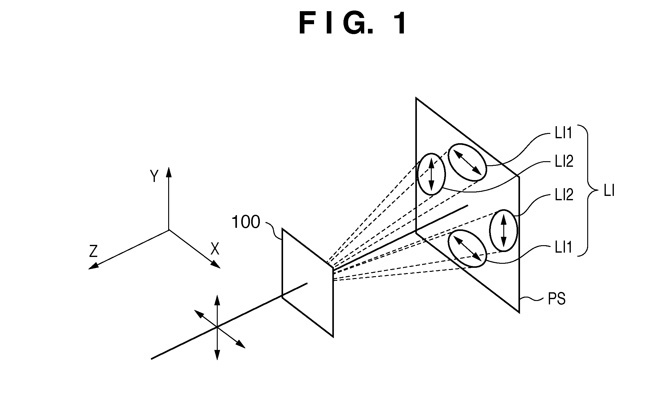
[0035]FIG. 1 is a view for explaining a computer generated hologram 100 according to one aspect of the present invention. As shown in FIG. 1, the computer generated hologram 100 forms a light intensity distribution (reconstructed image) LI on a predetermined plane PS (e.g., at the aperture position) by giving a phase distribution to the wavefront of incident light. The computer generated hologram 100 gives different phase distributions to the wavefront of X-polarized light serving as linearly polarized light in a first direction (linearly polarized light whose polarization direction is the first direction), and that of Y-polarized light serving as linearly polarized light in a second direction (linearly polarized light whose polariz...


PUM


Abstract

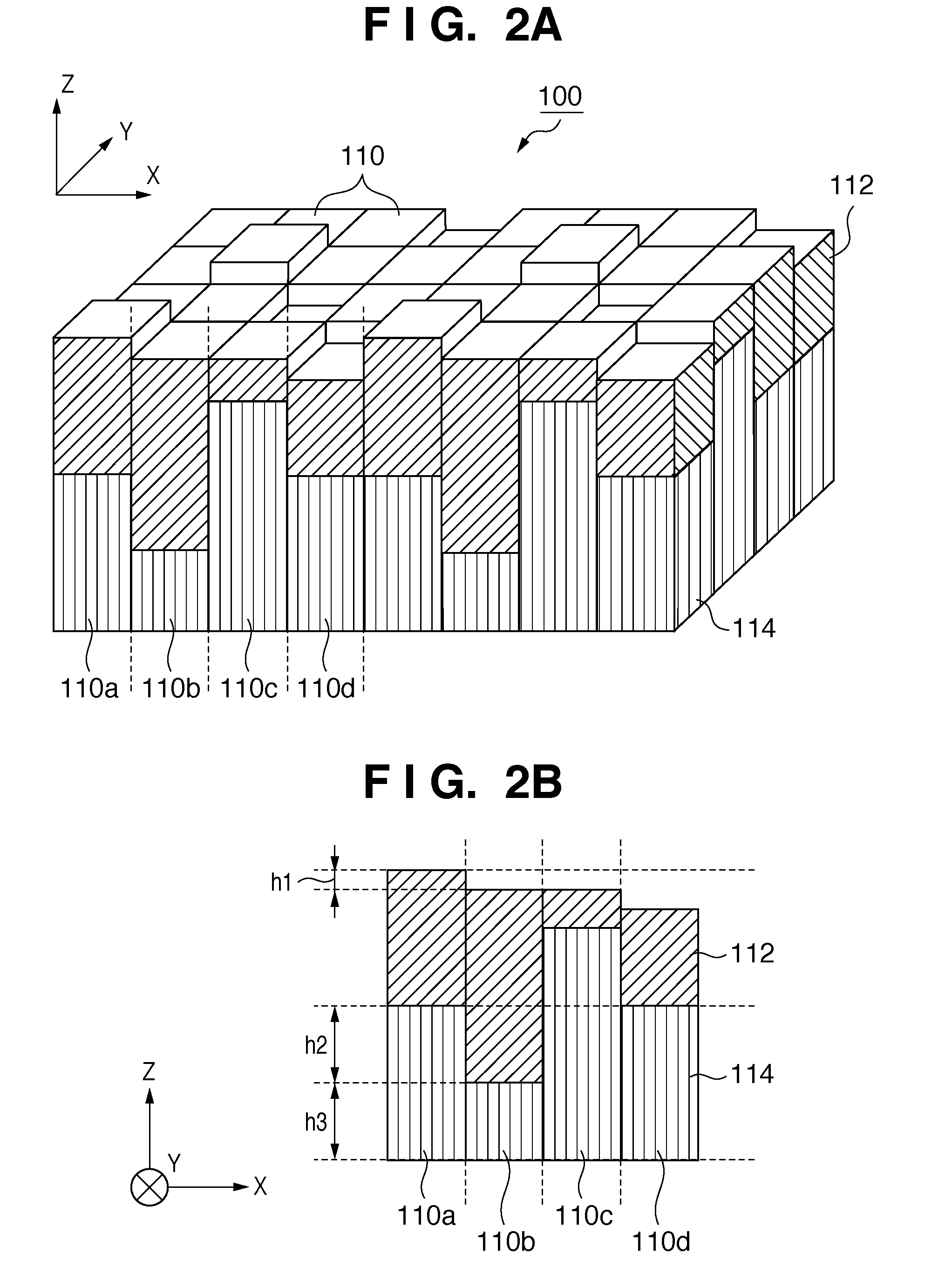
The present invention provides a computer generated hologram which forms a light intensity distribution on a predetermined plane by giving a phase distribution to a wavefront of incident light, comprising an anisotropic layer whose refractive index with respect to linearly polarized light in a first direction is different from a refractive index of the anisotropic layer with respect to linearly polarized light in a second direction perpendicular to the linearly polarized light in the first direction, and an isotropic layer whose refractive index with respect to the linearly polarized light in the first direction is equal to a refractive index of the isotropic layer with respect to the linearly polarized light in the second direction.

Description

BACKGROUND OF THE INVENTION[0001]1. Field of the Invention[0002]The present invention relates to a computer generated hologram, an exposure apparatus, and a device fabrication method.[0003]2. Description of the Related Art[0004]A projection exposure apparatus has conventionally been employed to fabricate, for example, a micropatterned semiconductor device such as a semiconductor memory or logic circuit by using photolithography. The projection exposure apparatus projects and transfers a circuit pattern formed on a reticle (mask) onto, for example, a wafer via a projection optical system.[0005]A resolution R of the projection exposure apparatus is given by:R=k1×(λ / NA)   (1)where λ is the exposure light wavelength, NA is the numerical aperture of the projection optical system, and k1 is a process constant determined by, for example, a development process.[0006]The shorter the exposure light wavelength or the higher the NA of the projection optical system, the better the resolution. Ho...

Claims


Application Information

Patent Timeline
IPC IPC(8): G03H1/08G03H1/00
CPCG02B5/32G03H2240/42G03F7/70566G03H1/0244G03H1/0272G03H1/08G03H1/0891G03H2001/2276G03H2222/31G03H2223/20G03H2240/24G03H2240/43G03H2260/63G03H2270/52G03H1/2249G03H2210/20G03H2240/41G03F7/70108G03H2001/0495
Inventor MATSUBARA, ISAO
Owner CANON KK
Learn More