Thermal distortion compensation for laser mirrors

a laser mirror and distortion compensation technology, applied in the direction of mirrors, laser details, active medium materials, etc., can solve the problem of concave mirrors becoming more concave, and achieve the effect of worsening mirror distortion

Inactive Publication Date: 2009-02-05
COHERENT INC
View PDF17 Cites 12 Cited by
  • Summary
  • Abstract
  • Description
  • Claims
  • Application Information

AI Technical Summary

Benefits of technology

[0017]The subject invention addresses thermal mirror distortion using the bimetallic effect to improve rather than worsen mirror distortion. In a preferred embodiment, the end header assemblies of the laser housing are defined by a flange upon which is mounted a mirror support. An elongated mirror element is mounted to the support. The mirror el

Problems solved by technology

In this case, the bimetallic effect tends to c

Method used


Image

  • Thermal distortion compensation for laser mirrors
  • Thermal distortion compensation for laser mirrors
  • Thermal distortion compensation for laser mirrors

Examples


Embodiment Construction

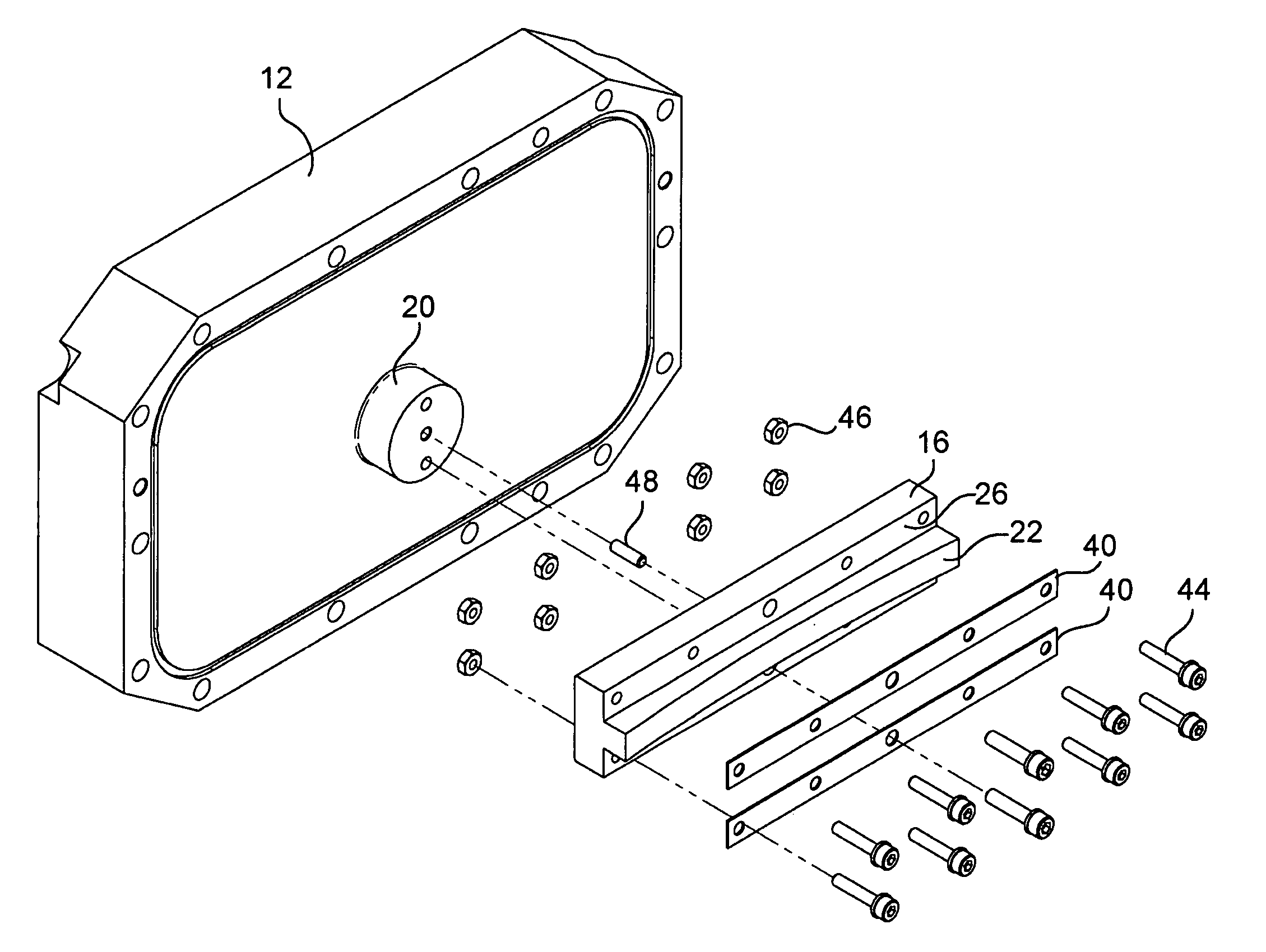
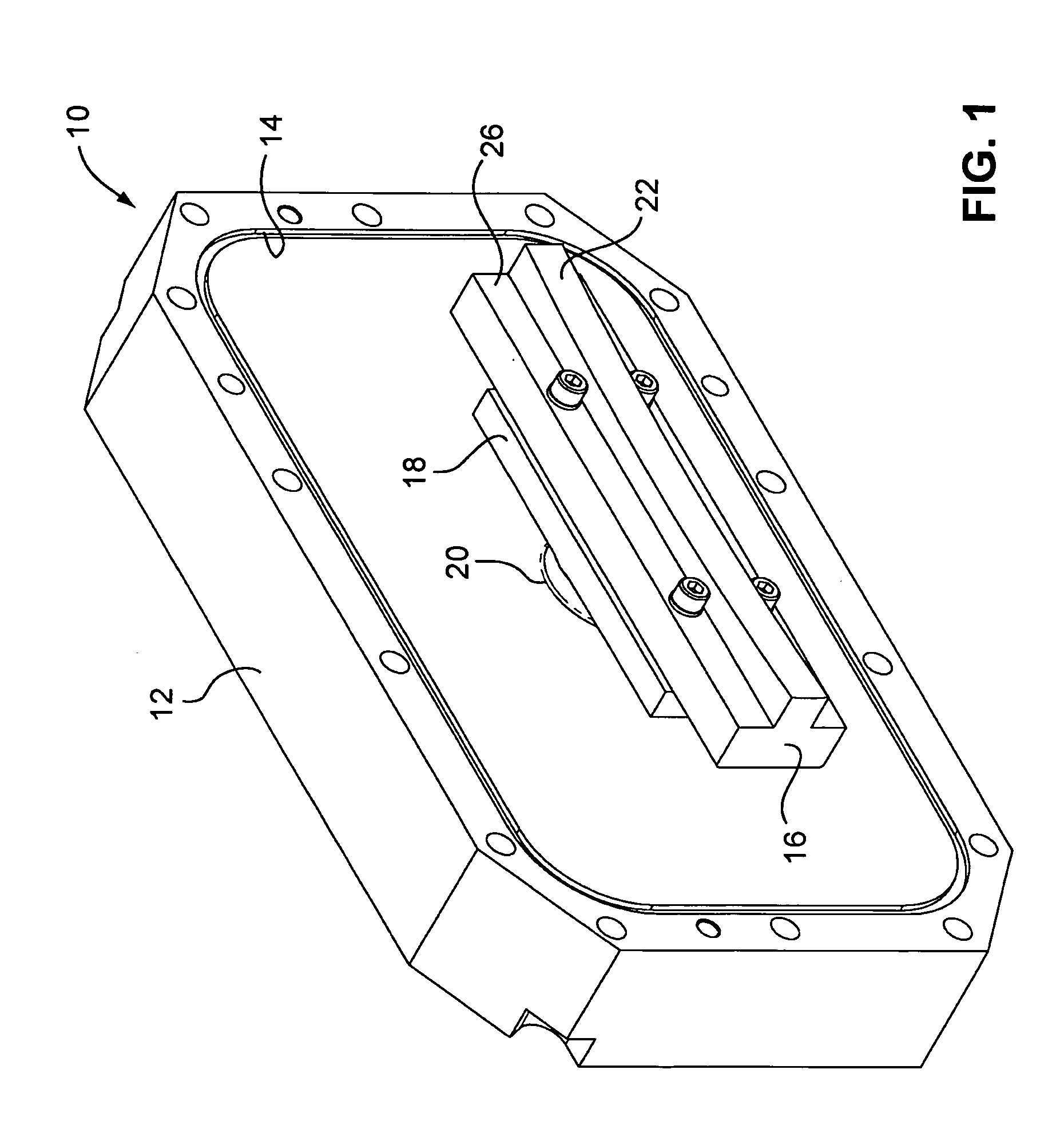
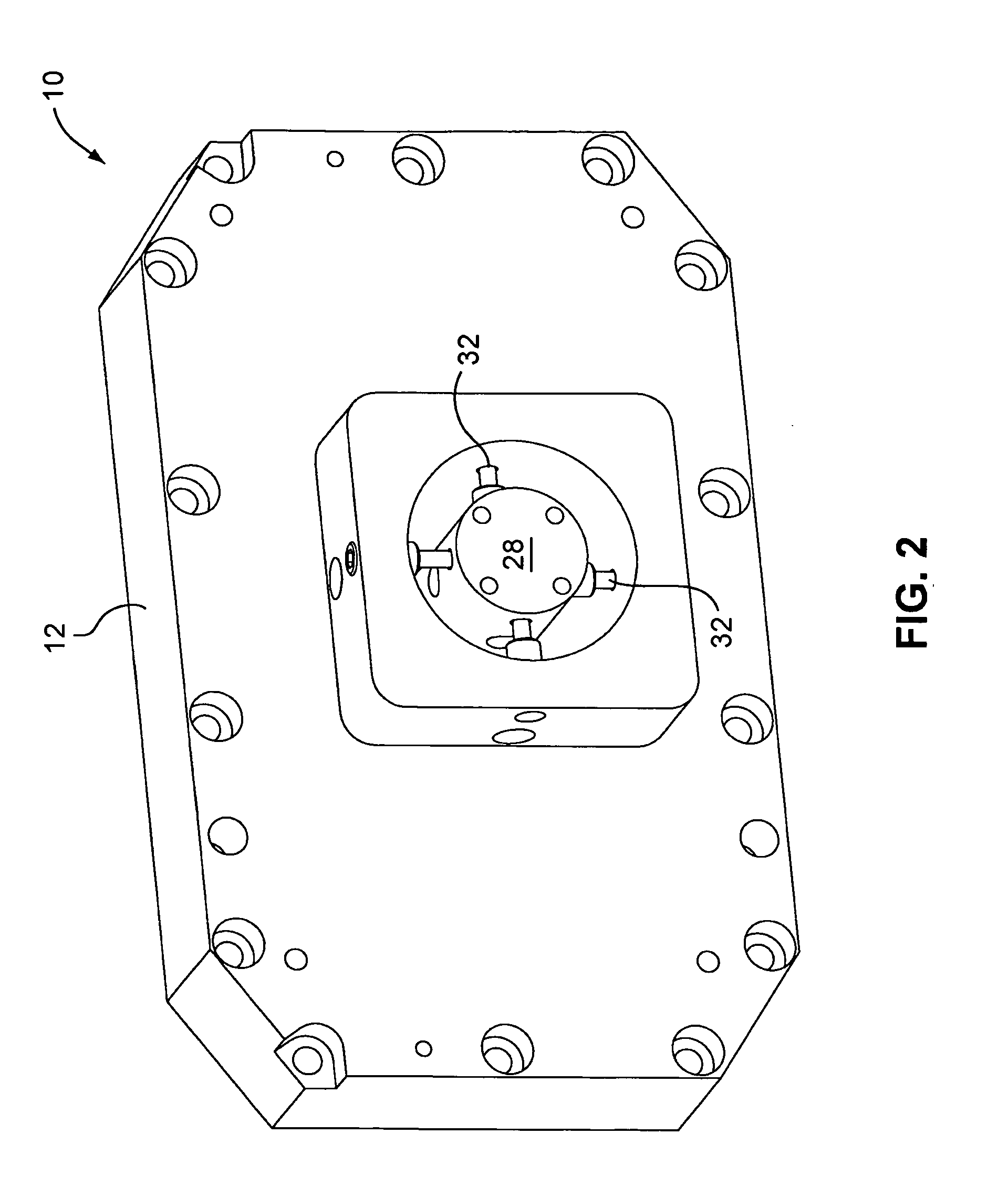
[0031]FIGS. 1 and 2 illustrate the header assembly 10 we have used in our experimental lasers for mounting a curved mirror forming a part of a negative branch unstable resonator of a CO2 slab laser.

[0032]The header assembly includes an aluminum flange 12 which is bolted onto the main housing to hermetically seals the laser tube housing chamber containing the electrodes, the CO2 gas mixture of CO2:N2:He:Xe, and the resonators mirrors. An O-ring 14 provides the hermetical seal. Commonly owned U.S. patent application Ser. No. 12 / 079,296 filed Mar. 26, 2008 (incorporated by reference) illustrates an example of a laser tube housing to which the flange disclosed herein can be attached. (See also U.S. Pat. No. 5,140,606 cited above).

[0033]A copper mirror 16 is mounted onto an aluminum mirror base 18 which in turn is connected to raised inside surface 20 of the aluminum flange. The mirror 16 includes an elongated, highly polished concave region 22 which defines the reflecting surface of the...


PUM


Abstract

A laser mirror assembly is disclosed with improved pointing stability. An elongated mirror includes a concave reflecting portion. A pair of elongated planar portions extend parallel to the concave reflecting portion on either side thereof. The planar portions are stepped down from the reflecting portion. The mirror is formed from copper. A pair of stainless steel strips are connected to planar portions. The bimetallic effect between the copper mirror and the stainless steel strips operates to counteract the warping of the mirror due to differential heating effects which arise during operation. In an alternate embodiment, a pair of aluminum strips are mounted on the rear surface of the mirror.

Description

PRIORITY[0001]This application claims priority to U.S. Provisional Application Ser. No. 60 / 962,740 filed Jul. 31, 2007, the disclosure of which is incorporated herein by reference.TECHNICAL FIELD[0002]This invention relates to high power carbon dioxide slab lasers. More specifically, the invention relates to a design of a mirror system which reduces thermal distortion and improves pointing stability.BACKGROUND[0003]The subject invention relates to high power diffusion cooled carbon dioxide slab lasers. An example of such a laser can be found in commonly owned U.S. Pat. No. 5,140,606 incorporated herein by reference. These lasers include a pair of rectangular metal electrodes mounted within a sealed housing containing the laser gas. The electrodes are spaced closely together to define a slab shaped discharge region. RF power is used to excite the gas to generate laser light.[0004]These types of lasers typically use a hybrid optical resonator which has an unstable resonator in the wid...

Claims


Application Information

Patent Timeline
IPC IPC(8): H01S3/08
CPCG02B7/182H01S3/0401H01S3/0346
Inventor NEWMAN, LEON A.SEGUIN, VERNON A.LAUGHMAN, LANNYPAPANIDE, ADRIAN
Owner COHERENT INC
Why Eureka
Try Eureka