Amplifier circuit and wireless communication device
a wireless communication device and amplifier technology, applied in amplifiers, amplifiers with semiconductor devices/discharge tubes, amplifiers, etc., can solve the problems of low gain distortion characteristic, low gain gain gain gain drop, and inability to solve simultaneously, so as to prevent gain loss and improve distortion characteristic
- Summary
- Abstract
- Description
- Claims
- Application Information
AI Technical Summary
Benefits of technology
Problems solved by technology
Method used
Image
Examples
embodiment 1
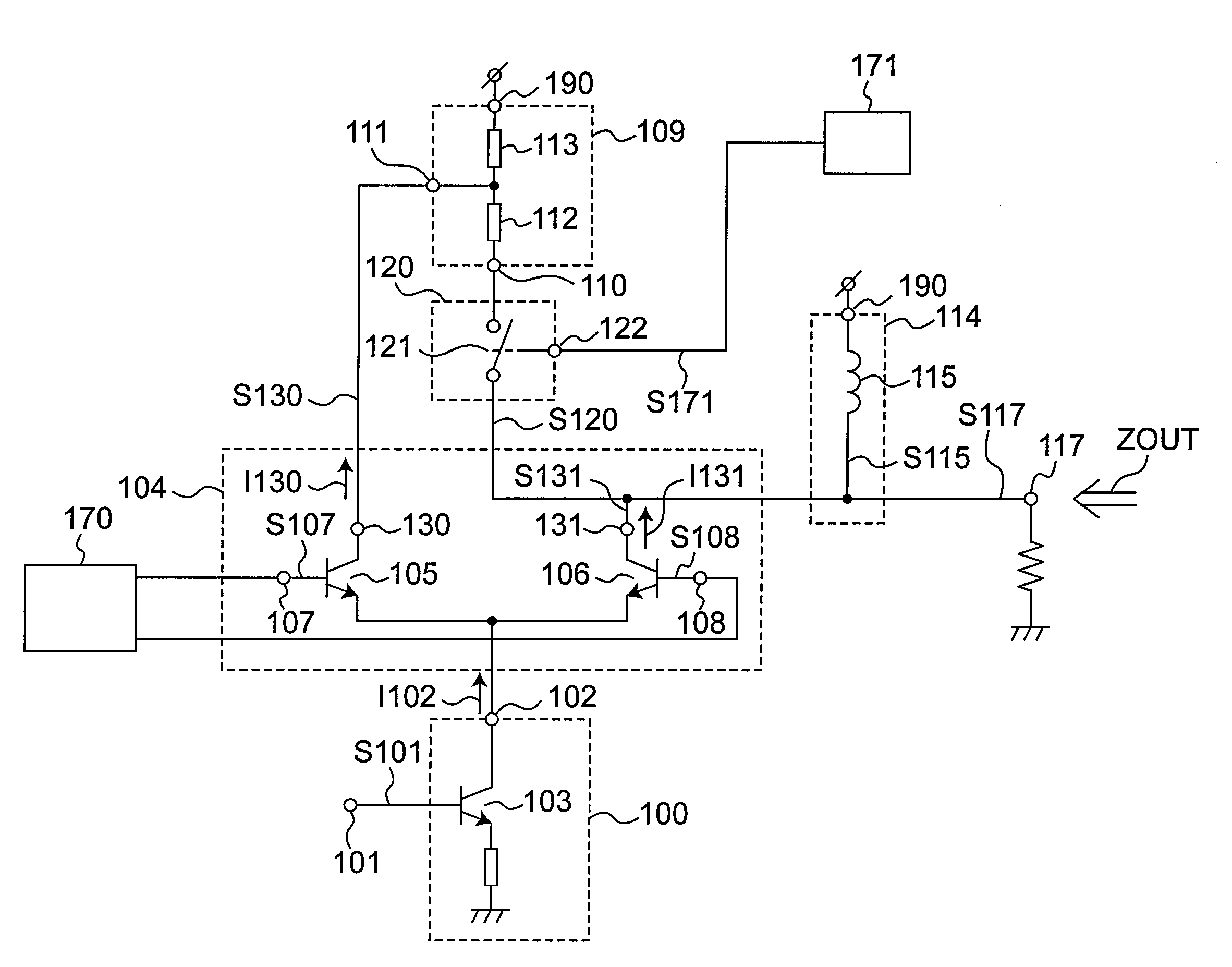
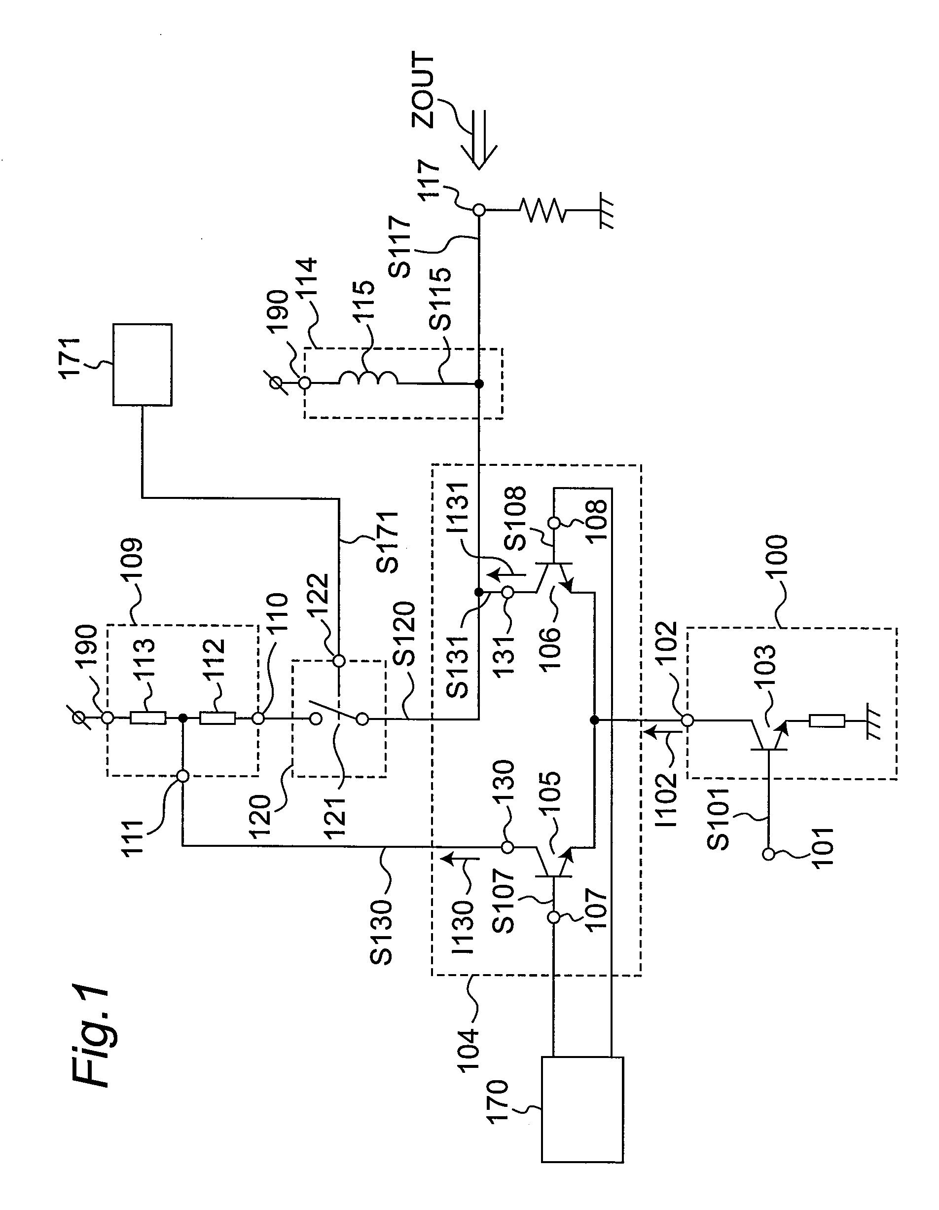
[0055]FIG. 1 is a circuit diagram of an amplifier circuit according to a first embodiment of the invention. As shown in FIG. 1 a high frequency signal S101 to be amplified is input to a current conversion circuit 100 through an input pin 101. The high frequency signal S101 is received at the base of a grounded-emitter transistor 103, and a signal current I102 corresponding to the high frequency signal S101 is then output through the collector of the transistor 103 from the output node 102 of the current conversion circuit 100.
[0056]The signal current I102 is then input to a gain control circuit 104 connected in common to the output node 102. The gain control circuit 104 consists of transistors 105 and 106 having the emitters connected in common. The gain control circuit 104 selectively outputs the signal current I102 to the collectors 130, 131 of the transistors 105 and 106, respectively, based on the control signals S107, S108 from a control signal generating circuit 170 applied to...
embodiment 2
[0067]A second embodiment of the invention is described next focusing on the differences with the first embodiment. Other aspects of the arrangement, operation, and effect of the second embodiment are the same as in the first embodiment, and further description thereof is omitted below.
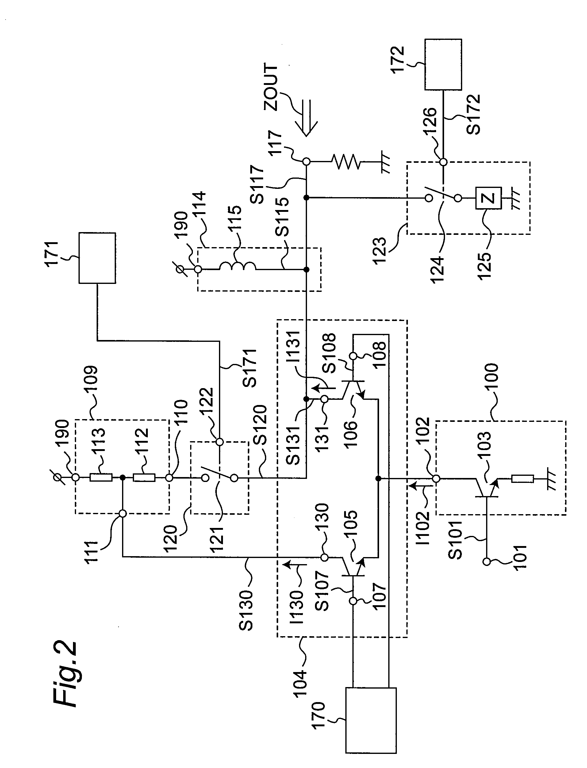
[0068]FIG. 2 is a circuit diagram of an amplifier circuit according to a second embodiment of the invention. Compared with the amplifier circuit of the first embodiment, this embodiment additionally has a variable impedance circuit 123 connected between the collector 131 of the gain control circuit 104 and the output pin 117.
[0069]The variable impedance circuit 123 has an impedance device 125 with a predetermined impedance, and a switch 124 that turns on / off electrically based on a control signal S172 applied from a control signal generating circuit 172.
[0070]In general, high frequency signals used for wireless communication have an extremely short wavelength, and some measures of reducing signal loss...
embodiment 3
[0084]A third embodiment of the invention is described next focusing on the differences with the first and second embodiments. Other aspects of the arrangement, operation, and effect of the third embodiment are the same as in the first and second embodiments, and further description thereof is omitted below.
[0085]FIG. 10 is a circuit diagram of an amplifier circuit according to a third embodiment of the invention. Compared with the amplifier circuit of the first embodiment, this embodiment additionally has a bypass circuit 150 inserted between the input pin 101 and output pin 117. The bypass circuit 150 has a switch 152 that switches on / off according to the control signal S175 input from the control signal generating circuit 175, and a capacitor 151 used to cut the dc voltage from the input pin 101.
[0086]Wireless communication devices are designed to be carried around freely and at times are used near the communication base station. Because signals significantly exceeding the limite...
PUM
 Abstract
Description
Claims
Application Information
 - R&D
- Intellectual Property
- Life Sciences
- Materials
- Tech Scout
- Unparalleled Data Quality
- Higher Quality Content
- 60% Fewer Hallucinations
Browse by: Latest US Patents, China's latest patents, Technical Efficacy Thesaurus, Application Domain, Technology Topic, Popular Technical Reports.
© 2025 PatSnap. All rights reserved.Legal|Privacy policy|Modern Slavery Act Transparency Statement|Sitemap|About US| Contact US: help@patsnap.com


