Data coupler

a data coupler and data technology, applied in the direction of duplex signal operation, power distribution line transmission, near-field system using receivers, etc., can solve the problems of high power resistance, large size of the coupler itself, and difficulty in installing the data coupler onto the electric power line, so as to achieve the effect of convenient installation

Inactive Publication Date: 2009-02-05
MURATA MFG CO LTD
View PDF12 Cites 10 Cited by
  • Summary
  • Abstract
  • Description
  • Claims
  • Application Information

AI Technical Summary

Benefits of technology

[0007]To overcome the problems described above, preferred embodiments of the present invention provide a small-size data coupler to be used in a data communication system and including an electric power line that can be easily installed.
[0009]By arranging the antenna adjacent to the electric power line without electrically connecting the antenna to the electric power line in a DC arrangement, a radio-frequency signal that is superimposed on the electric power line is supplied to the communication device and a radio-frequency signal from the communication device is supplied to the electric power line. Since only a radio-frequency signal is exchanged without causing the antenna to be electrically connected in a DC arrangement to the electric power line, the data coupler is not required to withstand high voltages and the size thereof can be reduced. In addition, since the antenna is arranged along the electric power line, installation of the antenna can be easily performed.
[0011]The antenna may preferably be arranged adjacent to the electric power line with only an insulator film of the electric power line therebetween. Alternatively, the antenna may be arranged adjacent to a metal wire that is wound around the electric power line. In this case, the antenna may be arranged adjacent to one end of the metal wire. Alternatively, the antenna may be arranged adjacent to the metal wire that is wound around the electric power line such that winding directions on a hot side and a cold side of the electric power line are opposite to each other. When the antenna is arranged adjacent to the metal wire that is wound around the electric power line such that the winding directions on the hot side and the cold side of the electric power line are opposite to each other, due to a differential operation of the metal wire, electromagnetic waves are not emitted from the metal wire. Thus, transmission of energy can be efficiently performed.
[0013]According to preferred embodiments of the present invention, since only a radio-frequency signal is exchanged without causing an antenna to be electrically connected in a DC arrangement to an electric power line, the data coupler is not required to withstand high voltages and the size thereof can be reduced. In addition, since the antenna is simply arranged along the electric power line or the antenna is simply arranged adjacent to a metal wire that is wound around the electric power line, installation of the antenna can be easily performed.

Problems solved by technology

However, since an alternating current of about 100 V from an electric power line must flow in this type of data coupler, use of a copper wire that withstands high power is required.
Thus, there is a problem in that the size of the coupler itself must be increased.
In addition, since a data coupler must be directly connected to an electric power line, there is another problem in that it is difficult to install the data coupler onto the electric power line.

Method used


Image

  • Data coupler
  • Data coupler
  • Data coupler

Examples


first preferred embodiment

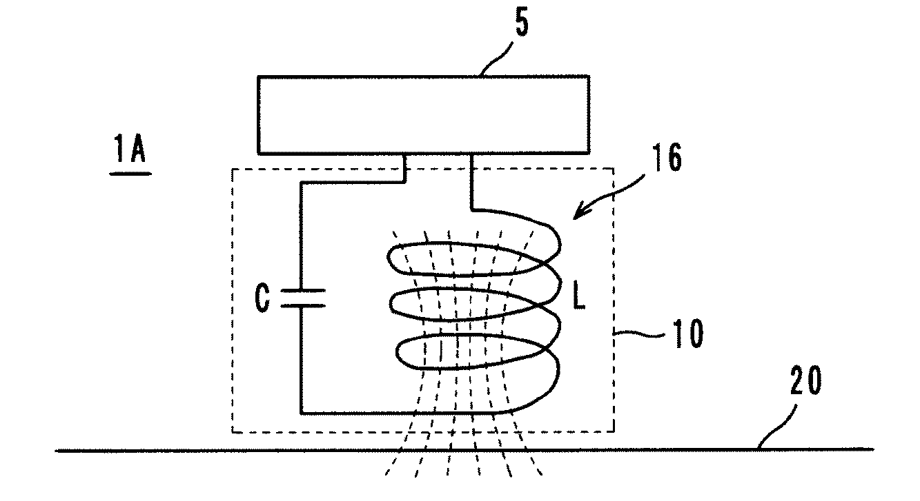
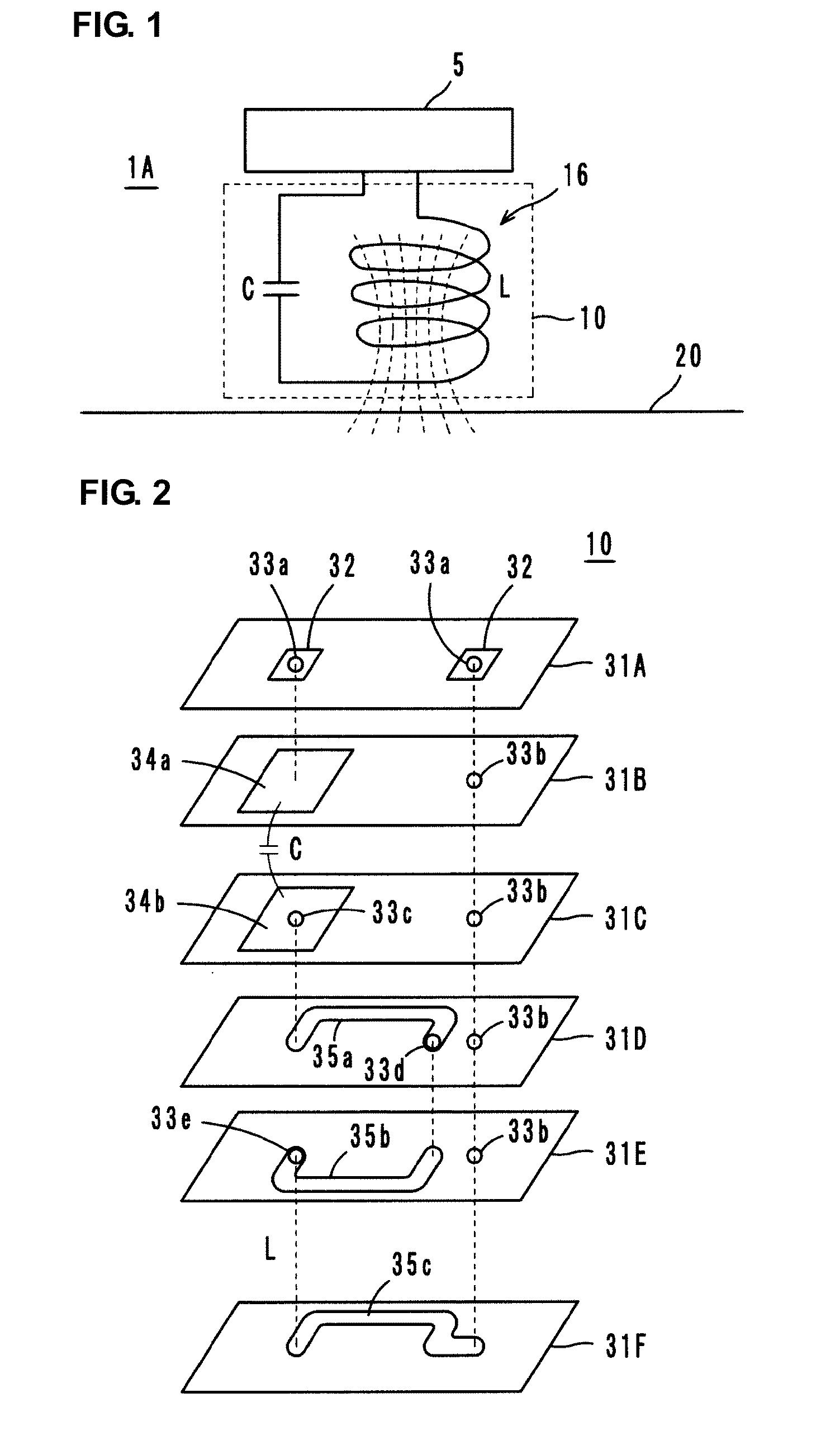
[0023]A data coupler 1A according to a first preferred embodiment includes an equivalent circuit shown in FIG. 1. In the data coupler 1A, a resonant circuit 16 is included in an antenna substrate 10. The antenna substrate 10 is arranged adjacent to a commercial electric power line 20 such that the antenna substrate 10 is not electrically connected in a DC arrangement to the electric power line 20. In addition, a modem 5, which is a communication device having a data processing function, is connected to the antenna substrate 10.

[0024]The resonant circuit 16 is an LC series resonant circuit including an inductance element L and a capacitance element C. The winding axis of a coil-shaped electrode pattern, which defines the inductance element L, is substantially perpendicular to the electric power line 20. The resonant circuit 16 is primarily magnetically coupled to the electric power line 20.

[0025]The resonant circuit 16 is a circuit arranged to supply a transmission signal having a sp...

second preferred embodiment

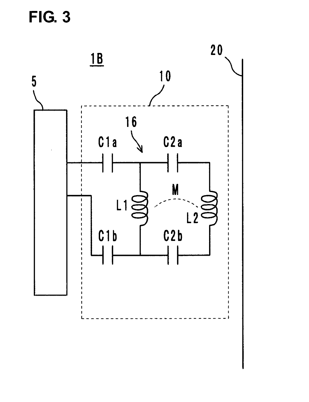
[0030]A data coupler 1B according to a second preferred embodiment includes an equivalent circuit shown in FIG. 3. In the data coupler 1B, the resonant circuit 16 includes inductance elements L1 and L2 that are magnetically coupled to each other. The inductance element L1 is connected to the modem 5 with capacitance elements C1a and C1b therebetween and is connected substantially in parallel to the inductance element L2 with capacitance elements C2a and C2b therebetween. In other words, the resonant circuit 16 includes an LC series resonant circuit including the inductance element L1 and the capacitance elements C1a and C1b, and an LC series resonant circuit including the inductance element L2 and the capacitance elements C2a and C2b. The LC series resonant circuits are coupled to each other by magnetic coupling, which is represented by M in FIG. 3. Both of the inductance elements L1 and L2 are magnetically coupled to the electric power line 20.

[0031]More specifically, as shown in a...


PUM


Abstract

A data coupler includes an antenna substrate that is not electrically connected in a DC arrangement to an electric power line, is arranged adjacent to the electric power line, and is connected to a modem. A resonant circuit including an inductance element and a capacitance element is provided in the antenna substrate. In the resonant circuit, the inductance element is magnetically coupled to the electric power line. The resonant circuit transmits a radio-frequency signal superimposed on the electric power line to the modem. The resonant circuit also transmits a transmission signal from the modem to the electric power line.

Description

BACKGROUND OF THE INVENTION[0001]1. Field of the Invention[0002]The present invention relates to a data coupler, and more particularly, to a data coupler to perform communication using an electric power line.[0003]2. Description of the Related Art[0004]Various data couplers to couple data between an electric power line and a communication device, such as a modem, have been used as data communication systems using electric power lines. For example, a data coupler including an inductive coupler that includes an electric power line conductor as a primary winding, a capacitor connected across a secondary winding of the inductive coupler to create a resonant circuit with the secondary winding at a frequency within a desired frequency band, and an impedance matching transformer to connect a communication device to the secondary winding is disclosed in Japanese Unexamined Patent Application Publication (Translation of PCT Application) No. 2006-503504.[0005]In the data coupler, a parallel r...

Claims


Application Information

Patent Timeline
Patent Type & Authority Applications(United States)
IPC IPC(8): H04B1/38H01P1/04H04B3/56H04B5/02
CPCH04B3/56H04B2203/5483H04B5/0093H04B5/0018
Inventor KATO, NOBORUKIMURA, IKUHEI
Owner MURATA MFG CO LTD
Why Eureka
Try Eureka