Eureka AIR delivers breakthrough ideas for toughest innovation challenges, trusted by R&D personnel around the world.

Image-blur compensating device and image pickup apparatus

Inactive Publication Date: 2009-02-05
SONY CORP
View PDF6 Cites 18 Cited by
  • Summary
  • Abstract
  • Description
  • Claims
  • Application Information

AI Technical Summary

Benefits of technology

[0015]Since either of the electromagnetic actuator drives and position sensor detects the shift lens electromagnetically, the magnetic field generated by the electromagnetic actuator may interfere with the hall element as the position sensor, thereby reducing the accuracy in detecting positions. If the image pickup apparatus includes the electromagnetic actuators and the position sensors that can be arranged so as to leave a sufficient distance therebetween to have no interference, the accuracy in detecting positions will not decrease. However, since recent trend in image pickup apparatus such as camcorders and electronic digital still cameras seems to reduce size thereof, the notion of leaving a sufficient distance between the actuator and the sensor may be accepted in production. Specifically, when the position sensor detects positions in the presence of the electromagnetic field effects generated by the electromagnetic actuator, the accuracy in compensating image-blur will be reduced due to decrease in the detection accuracy of the position sensor.
[0016]Thus, an embodiment of the invention intends to provide an image pickup apparatus having little interference between the actuators and the position sensors so as to compensate image-blur accurately.
[0018]As a result, the target displacement calculator calculates, as a result of compensating the amount of influence based on the position of the actuator on the position detected by the displacement detector, and compensates the amount of influence so as to eliminate the influence from the actuator, thereby accurately compensating the image-blur of images.
[0019]In the embodiments of the invention, the target displacement calculator calculates, as a result of compensating the amount of influence based on the position of the actuator on the position detected by the displacement detector, and compensates the amount of influence so as to remove the influence from the actuator, thereby accurately compensating the image-blur of images. Thus, image-blur is accurately compensated even though the actuator and the displacement detector are adjacently arranged, and an apparatus having an image-blur compensating mechanism can be reduced in size.

Problems solved by technology

There frequently occurs interference between actuators driving a shift lens and sensors in such an image pickup apparatus having the sensors detecting the pitch and yaw angles.
Since either of the electromagnetic actuator drives and position sensor detects the shift lens electromagnetically, the magnetic field generated by the electromagnetic actuator may interfere with the hall element as the position sensor, thereby reducing the accuracy in detecting positions.
Specifically, when the position sensor detects positions in the presence of the electromagnetic field effects generated by the electromagnetic actuator, the accuracy in compensating image-blur will be reduced due to decrease in the detection accuracy of the position sensor.

Method used


Image

  • Image-blur compensating device and image pickup apparatus
  • Image-blur compensating device and image pickup apparatus
  • Image-blur compensating device and image pickup apparatus

Examples


first embodiment

[0033]the invention will be described below with reference to FIG. 3 to FIG. 8. An image pickup apparatus according to the embodiment of the invention includes an image-blur compensating device configured to compensate an image-blur resulted from unintentional hand-movements in capturing an image. Various image pickup apparatuses such as camcorders, digital still cameras, and camera phone terminals can employ such an image-blur compensating device. For example, a digital camera 80 or a digital camera 90, an external appearance of which is shown by phantom lines in FIG. 7 or in FIG. 8 described later, can employ the image compensating device.

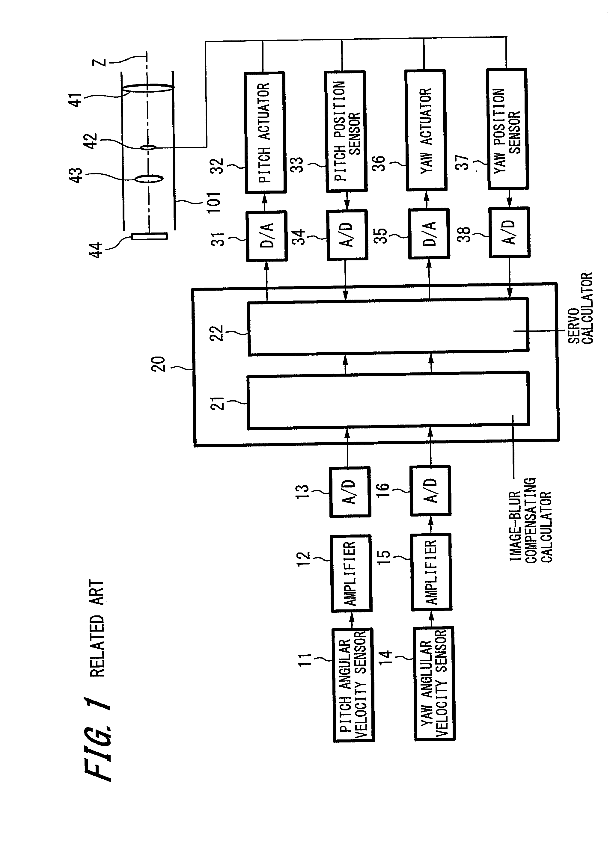
[0034]First, an overall configuration of the image pickup will be described with reference to FIG. 4. The image pickup apparatus includes a lens barrel 81 configured to capture images including fixation lenses, a zoom lens 84, a shift lens 104, a focus lens 86, and an imager 87 therein that are all aligned along the optical axis Z in this order. ...

fifth embodiment

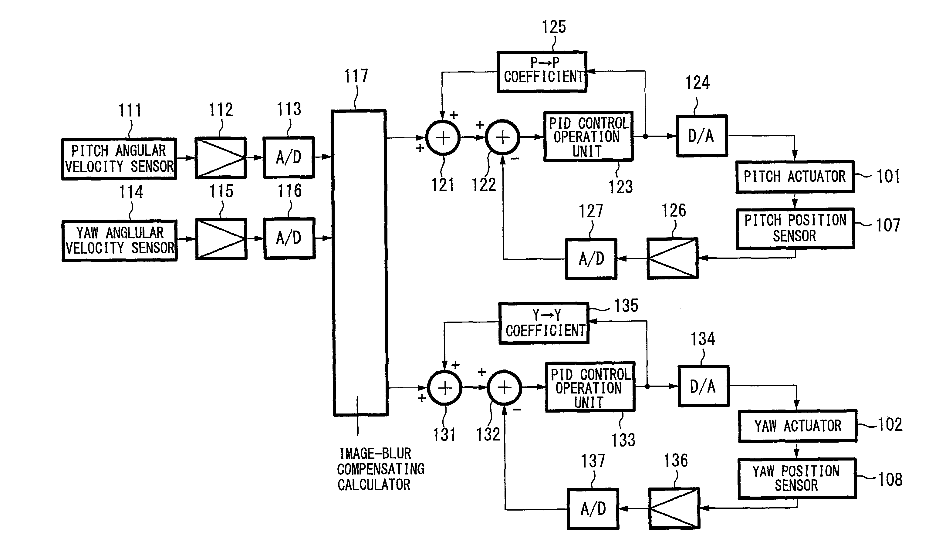
[0083]The configuration of the invention shown in FIG. 12 has fundamentally the same configuration of the control configuration illustrated in FIG. 11. In this embodiment, the instruction value of the pitch angle calculated by the image-blur compensation calculator 117 is supplied to an adder 142. The adder 142 adds thereto compensation values output by a zoom lens and focus lens positions output unit 141, and the resulting values output by the adder 142 are supplied to the adder 121. Further, the instruction value of the yaw angle calculated by the image-blur compensation calculator 117 is supplied to an adder 143. The adder 143 adds thereto compensation values output by the zoom lens and focus lens positions output unit 141, and the resulting values output by the adder 143 are supplied to the adder 131.

[0084]The zoom lens and focus lens positions output unit 141 computes a compensation value by compensating an amount of influence by actuators for driving the zoom lens on the instr...


PUM


Abstract

Disclosed is an image-blur compensating device including an optical axis changing unit changing an optical axis, an actuator driving the optical axis changing unit, a displacement detector detecting a position of the optical axis changed by the optical axis changing unit, an angular velocity detector detecting an angular velocity applied from outside, and a target displacement calculator calculating a driving amount when the actuator has driven the optical axis changing unit based on the angular velocity detected by the angular velocity detector and the position detected by the displacement detector. The target displacement calculator then obtains, as a result of compensating an amount of influence on the position of the optical axis, a driving amount when driving the actuator based on the calculated driving amount. The image-blur compensating device further includes a driver driving the actuator based on the driving amount calculated by the target displacement calculator.

Description

CROSS REFERENCES TO RELATED APPLICATIONS[0001]The present invention contains subject matter related to Japanese Patent Application JP 2007-202251 filed in the Japanese Patent Office on Aug. 2, 2007, the entire contents of which being incorporated herein by reference.BACKGROUND OF THE INVENTION[0002]1. Field of the Invention[0003]The invention relates to an image-blur compensating device configured to compensate blurred images due to, for example, unintentional movements of a user's hand holding a so-called image-blur compensation image pick up apparatus, and also to an image pickup apparatus having the image-blur compensating device such as digital still cameras or camcorders.[0004]2. Description of the Related Art[0005]When a user unintentionally moves her / his hand in capturing images using a related art digital still camera or camcorder, the captured images are blurred in response to hand trembling or wobbling, thereby significantly deteriorating the quality of the captured images...

Claims


Application Information

Patent Timeline
IPC IPC(8): G03B17/00
CPCG03B17/00H04N5/23287H04N5/23258H04N5/23248H04N23/68H04N23/6812H04N23/687
Inventor TAKAGI, HIDEOTAKAHASHI, TATSUYUKITAKAOKA, TOSHIFUMITAKEI, TOMOYA
Owner SONY CORP
Why Eureka
Eureka Blog
Learn More