
Tools and method for implanting a subcutaneous device

Inactive Publication Date: 2009-02-05
MEDTRONIC INC
View PDF14 Cites 28 Cited by
  • Summary
  • Abstract
  • Description
  • Claims
  • Application Information

AI Technical Summary

Benefits of technology

[0005]A method and apparatus is described which provides for an improved implantation of a minimally intrusive implantable system capable of communicating with an external device and having subcutaneous electrodes to measure a subcutaneous electrogram. The system includes a signal input means, a looping memory, detection circuitry, a circuit for controlling the memory. Furthermore, the system includes a housing design that enables minimal intrusion and adapted to be implanted using simple implant tools, enabling an efficient method to facilitate the implantation of the device.

Problems solved by technology

Syncopal events and arrhythmias of the heart are particularly problematic for diagnostic physicians to observe in patients.
Holter monitors are well known for monitoring electrocardiograms for periods of time amounting to days or perhaps a week, but these are bulky and are applied externally to the body and interfere with the patient's normal life, making them impractical for long-term use.
Further, patient compliance cannot always be guaranteed, and is a common problem in using the Holter devices.
Problems with external monitors and associated recorders also include inability of some patients to tolerate the attendant skin irritation.
Bulky or expensive special purpose devices may need to be available and maintained.
Any time a living body needs to have a long term monitoring of a physiologic event that is intermittent or infrequent or both, all these problems come into focus.
This has been expensive, limiting the use of the ILR and overly invasive to the patient requiring a subcutaneous implant of intracardiac monitors for simple recording functions.

Method used


Image

  • Tools and method for implanting a subcutaneous device
  • Tools and method for implanting a subcutaneous device
  • Tools and method for implanting a subcutaneous device

Examples


Embodiment Construction

[0026]A small and easy-to-implant, leadless ILR device will require a minimal incision size, which has patient benefit. Between ½ and 1 inch incisions are preferred to avoid trauma and scarring and reduce the chance of infection. For ease of insertion, the device should be easy to self-position, and preferably elongated in shape to maximize signal strength for a given volume by having electrodes spaced at far ends of the length. The general use, without limitation, of the device is long term ECG event monitoring.

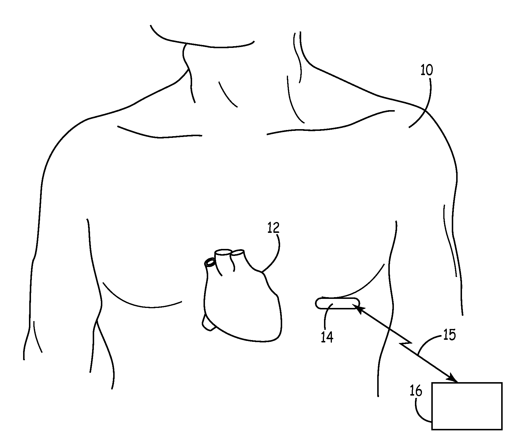
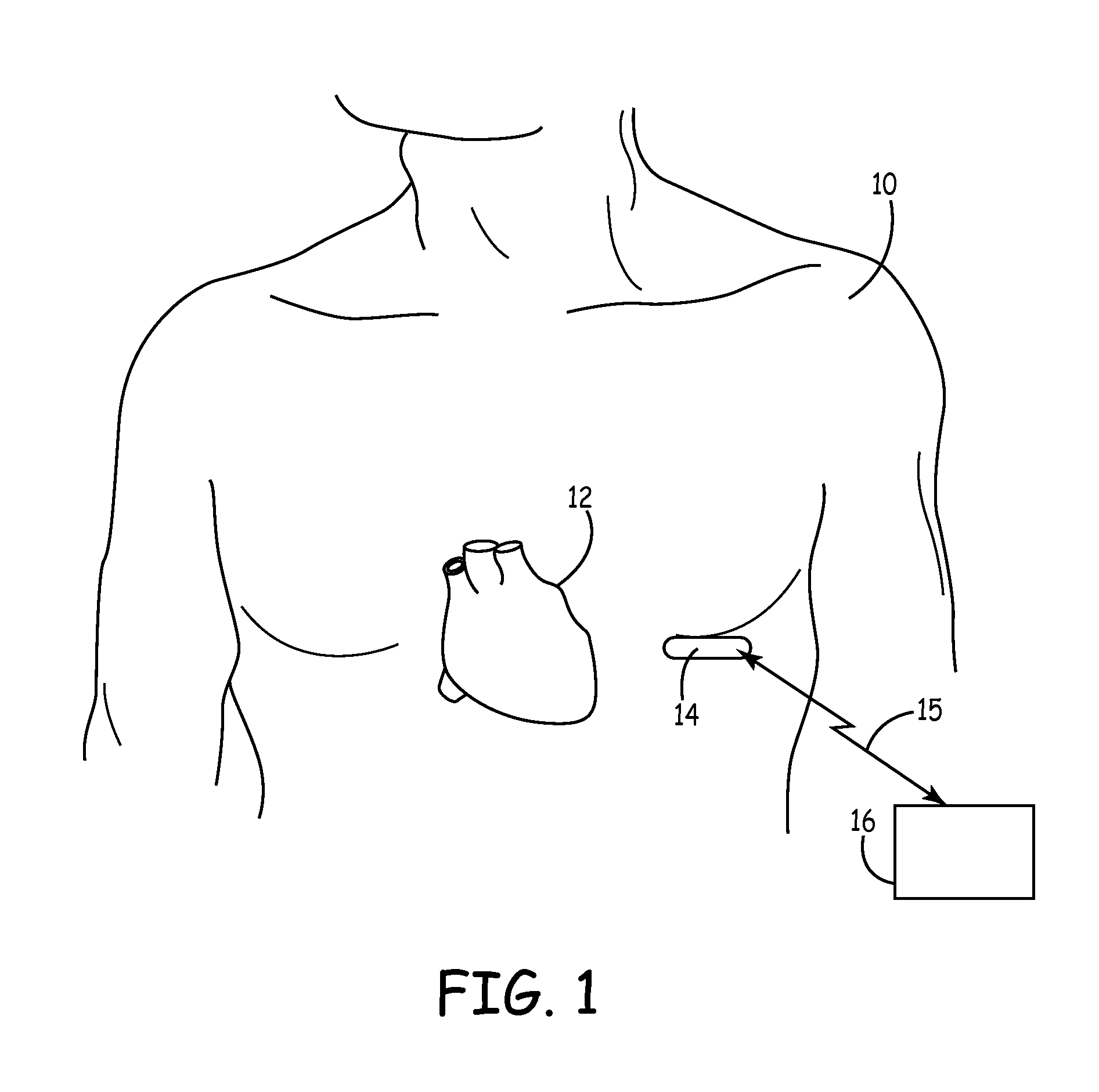
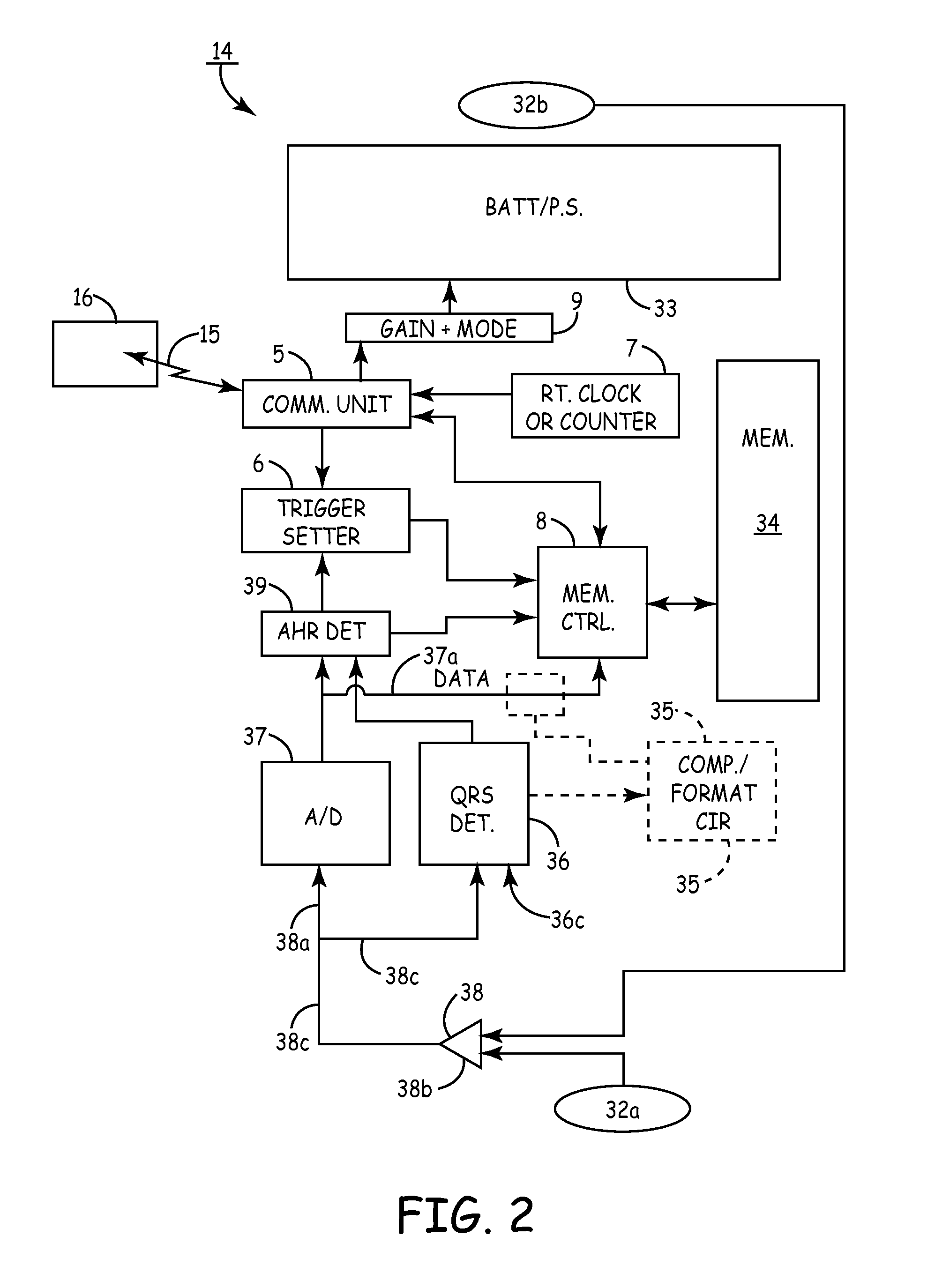
[0027]FIG. 1 is a frontal view of a patient 10 in whom an ILR 14 may be subcutaneously implanted with a typical location referenced thereon (other implant locations may be utilized). The ILR 14 senses cardiac electrical activation signals via electrodes (not shown in FIG. 1) from heart 12. A communication link 15 allows 2-way telemetry communication between ILR 14 and an external device (typically a programmer) 16. Programmer 16 and telemetry systems (15) suitable for use in...


PUM


Abstract

Several tools and simplified implant methods utilizing minimal surgical intrusion into a subject are disclosed for the proper inserting, advancement and positioning of a subcutaneous implantable medical device (IMD). A kit disclosed herein includes a poker for penetrating the skin and generating a small incision, a tissue spreader for increasing the incision width and an introducer and cannula for the proper insertion of the ILR subcutaneously. Diverse IMDs can be implanted using the kit, tools and methods included in the disclosure, including implantable pulse generators (IPGs), implantable loop recorders (ILRs) for collecting and transmitting cardiac activity signals and implantable cardioverter-defibrillators (ICDs) for delivering high voltage cardiac therapy via electrodes spaced from the myocardium.

Description

FIELD OF THE INVENTION[0001]The present invention generally relates to a minimally invasive implantation of implantable medical devices (IMD); such as, for instance a leadless subcutaneous implantable cardioverter-defibrillator or a cardiac monitor having segmented looping memory for storing physiologic ECG signal events, and the like. The invention is more particularly directed to implant and tunneling tools and methods for the implanting and positioning a subcutaneous ICD or heart monitor in a subject.BACKGROUND OF THE INVENTION[0002]Syncopal events and arrhythmias of the heart are particularly problematic for diagnostic physicians to observe in patients. These events, can be of short duration with sudden onset, and may come with little or no warning, while occurring very infrequently. Holter monitors are well known for monitoring electrocardiograms for periods of time amounting to days or perhaps a week, but these are bulky and are applied externally to the body and interfere wit...

Claims


Application Information

Patent Timeline
IPC IPC(8): A61B17/02A61N1/362
CPCA61B5/0031A61B5/0472A61M25/0662A61B17/3468A61B17/02A61B5/366
Inventor ANDERSON, KENNETH M.
Owner MEDTRONIC INC
Learn More