Detection of address decoder faults

a decoder and address technology, applied in the field of data processing systems, can solve the problems of increasing the likelihood of the occurrence of soft errors and/or hard errors in such memories, consuming more circuit area of ecc memory, and corrupting the data value concerned, so as to reduce the overhead associated with the operation and reduce the number of bits

Inactive Publication Date: 2009-02-05
ARM LTD
View PDF15 Cites 34 Cited by
  • Summary
  • Abstract
  • Description
  • Claims
  • Application Information

AI Technical Summary

Benefits of technology

[0011]The invention recognises that a word line signal generated by an address decoder to access a row of data values within a memory array can also be used to access data values indicative of the address of that row of memory cells. Thus, the data returned will include both the data values themselves and data indicative of the address of those data values. The data indicative of the address of those data values can then be compared within the input address which was supplied to the address decoder and any mismatch therebetween can be used to detect an error in the address decoder. Since the addresses associated with the rows of memory cells are static, the data identifying the addresses can be stored in a relatively efficient manner reducing the overhead associated with its storage.
[0012]Whilst it would be possible for different rows of memory cells to share common data identifying address values so as to reduce the number of bits which need to be provided in the data identifying the address values, such an arrangement would mean that in a small number of cases an address decoder fault could by coincidence access an incorrect row of memory cells that happens to have the correct address identifying data. Such a possibility can be avoided if each of the rows of memory cells has a different address identifying data associated therewith.
[0016]As previously mentioned memories can be provided with error correcting codes serving to detect errors within the data values stored therein and provide a facility for correcting small numbers of such errors. Such techniques can synergistically be used in combination with the present technique of storing address identifying data for the rows of memory cells. Thus, the error correcting codes provide protection for the data values stored and the address identifying data provides protection to ensure the correct data is accessed in response to an input address. These techniques used in combination provide a highly fault resistant and robust memory system.

Problems solved by technology

As process geometries scale to smaller sizes and operating voltages lower there is an increase in the likelihood of the occurrence of soft errors and / or hard errors within such memories, e.g. a strike from a charged particle inducing a disruption which changes the value of a bit being stored within a memory or a gate failing thereby corrupting the data value concerned.
Such ECC memory consumes more circuit area due to the need to store the error correcting codes in addition to the data of interest.
This additional overhead is disadvantageous in terms of cost, power consumption and efficiency, but is justified when the integrity of the data is important and a degree of fault tolerance is necessary, e.g. in a safety critical system, such as a car anti-lock break system.
Another more subtle problem which can arise with memories concerns the correct operation of the address decoder.
Within a safety critical system, such an error in address decoder operation could have severe consequences.
Whilst this is a superficially attractive proposal, it suffers from significant real life disadvantages.
The area overhead associated with having to provide a second address decoder is significant and disadvantageous.
In the case of address decoder malfunction, the data values are likely to be completely different to those intended to be covered by the error correcting code thus overwhelming any capacity of the error correcting code to correct those errors, and in some circumstances producing a false result in which the error correcting code by chance happens to match completely different data recovered as a consequence of the address decoder fault.
This level of potential error may be unacceptable in certain applications.

Method used


Image

  • Detection of address decoder faults
  • Detection of address decoder faults
  • Detection of address decoder faults

Examples


Embodiment Construction

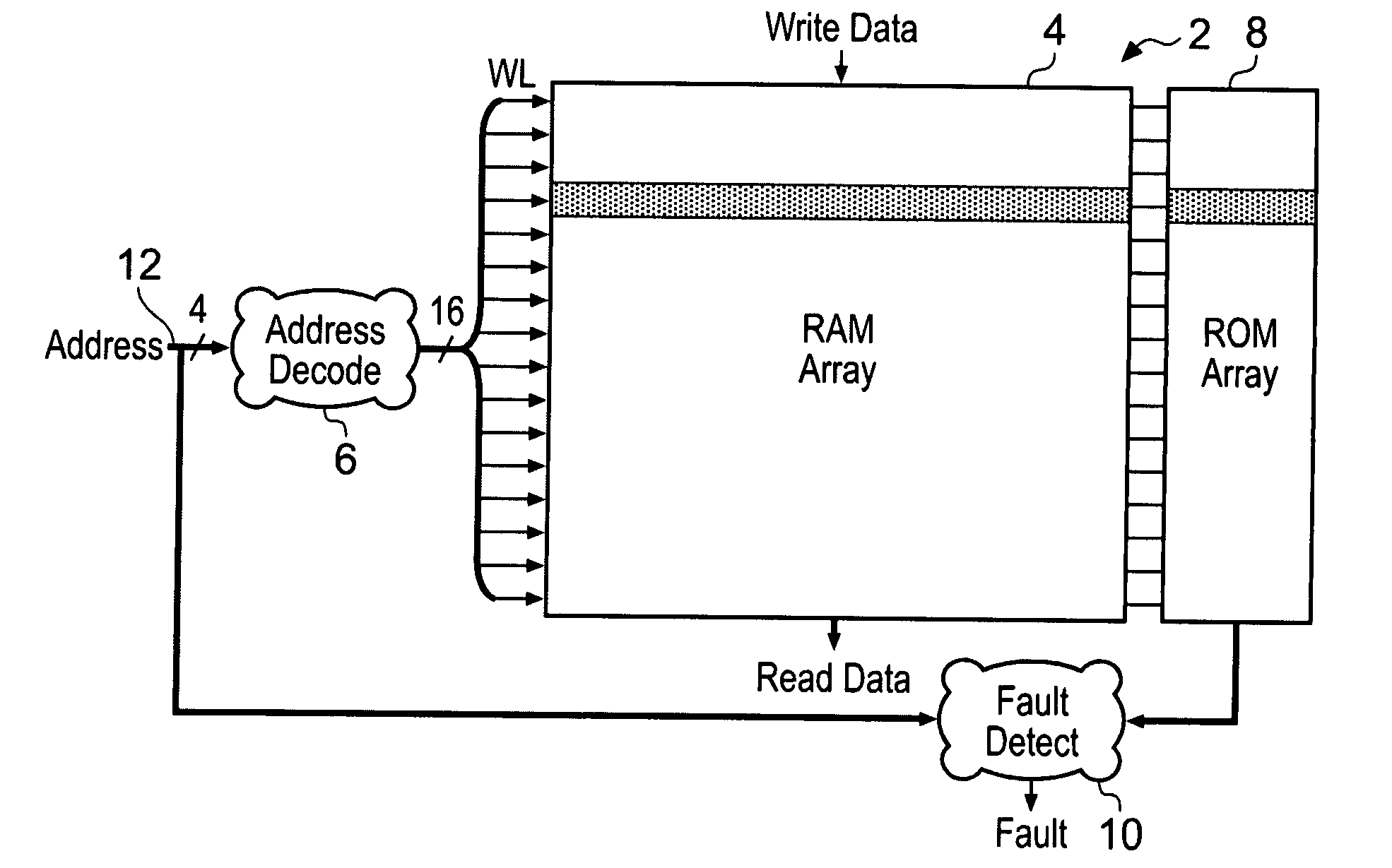
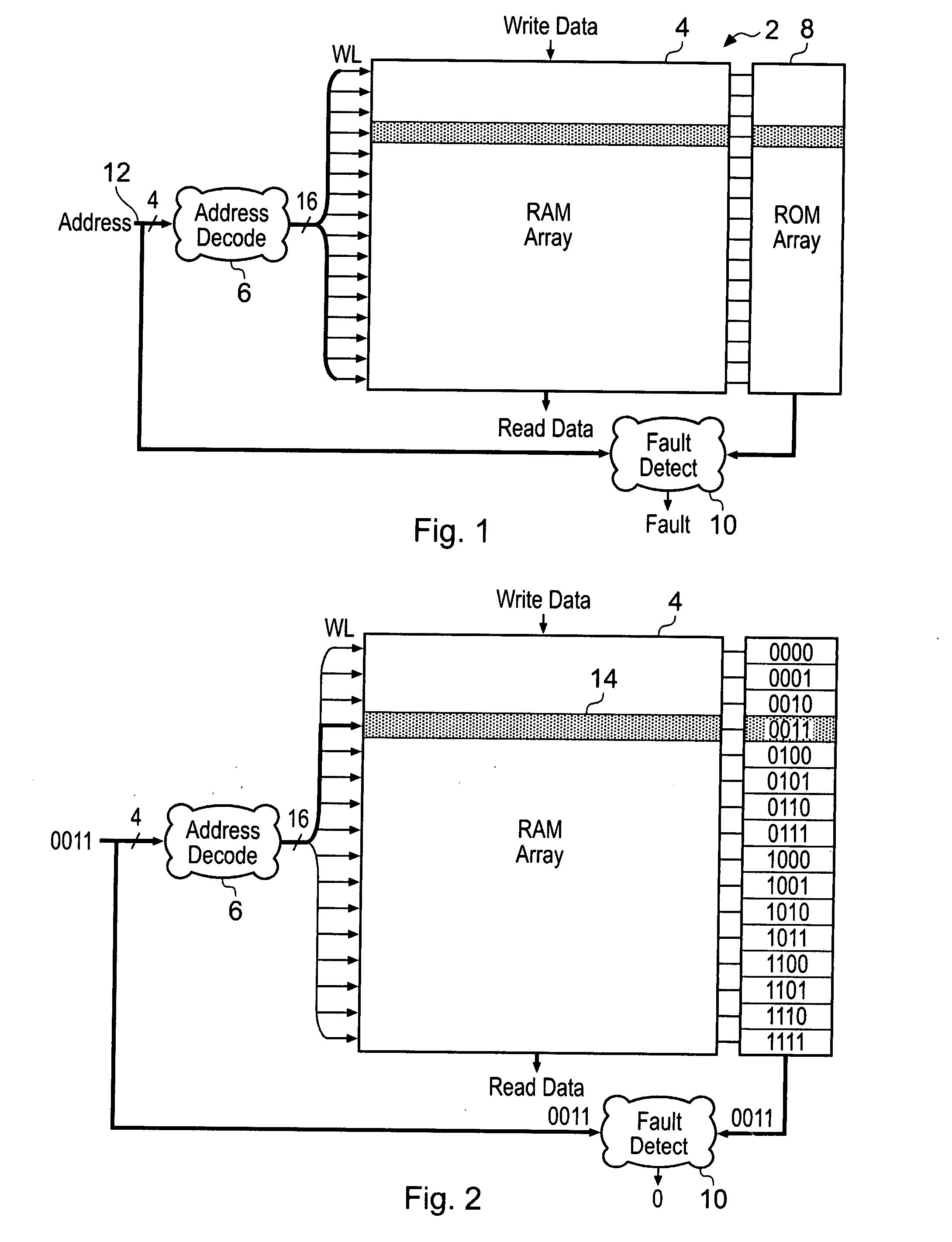
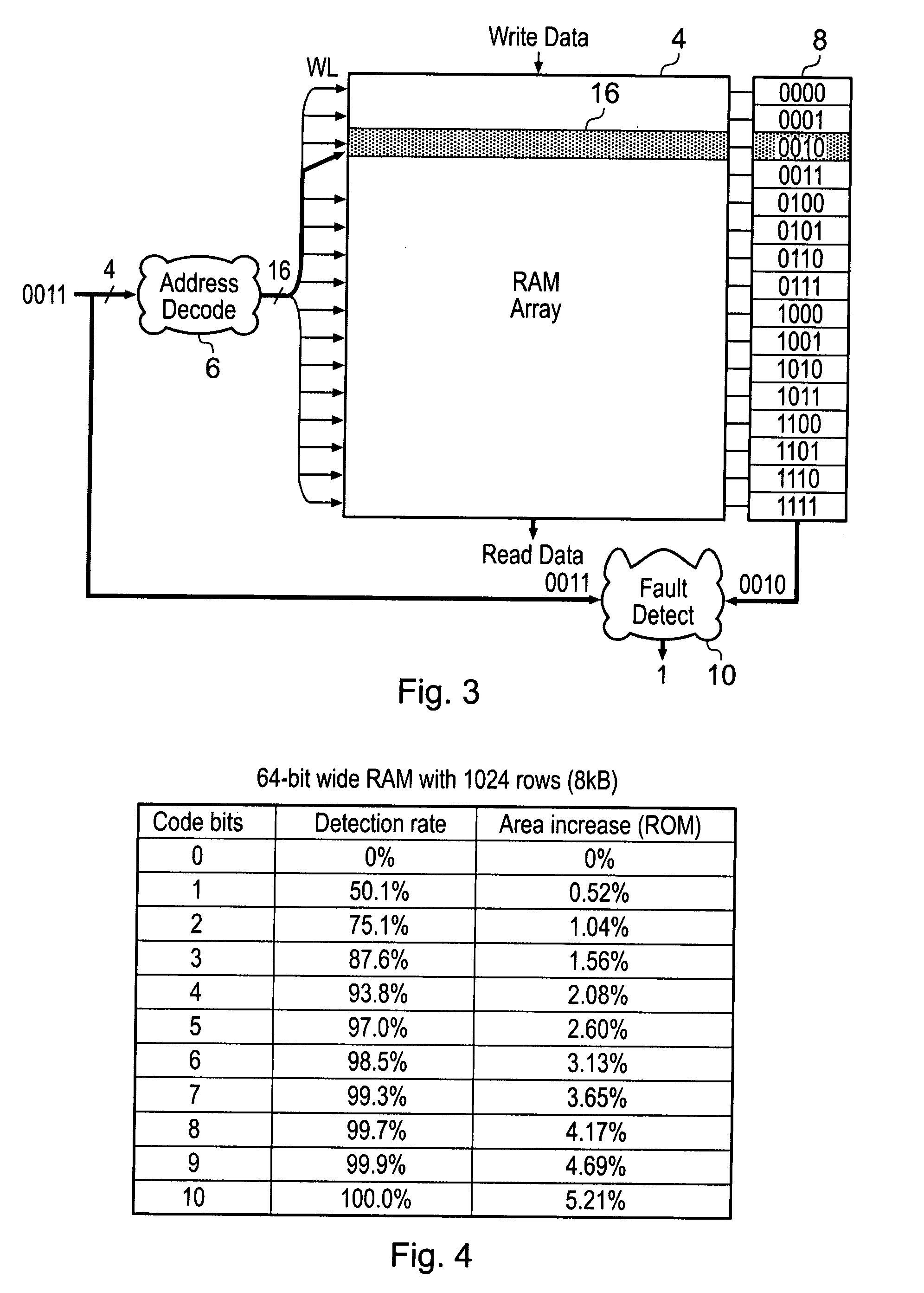
[0036]FIG. 1 illustrates a memory 2 comprising an array 4 of memory cells (not illustrated, but can have one of the standard forms of a RAM memory cell), an address decoder 6, a ROM array 8 storing address identifying data and a fault detecting circuitry 10. In operation, an input address is supplied upon address bus 12 and is decoded by the address decoder 6. In this example, the address is a 4-bit address allowing one of 16 different rows of memory cells within the array 4 to be selected by a corresponding word line signal WL. When the addressed row of memory cells is selected, then the data values therein can either be read or written in the standard way depending upon the particular operation being performed.

[0037]Associated with each row of memory cells within the array 4 are 4-bits of address identifying data stored within the ROM array 8. There is one group of 4-bits of address identifying data for each row of memory cells within the array 4. The individual address identifyin...


PUM


Abstract

A memory 2 is formed having an array of memory cells 4 arranged in rows 14. An address decoder 6 generates a word line signal WL in response to an input address to select one of the rows of memory cells for access. The word line signal also accesses address identifying data associated with the row of memory cells being accessed. This address identifying data is compared with the input address by fault detection circuitry 10. If a mismatch is detected, then this indicates a fault within the address decoder 6.

Description

BACKGROUND OF THE INVENTION[0001]1. Field of the Invention[0002]This invention relates to the field of data processing systems. More particularly, this invention concerns the detection of faults within address decoders used when accessing arrays of memory cells.[0003]2. Description of the Prior Art[0004]It is known to provide memories comprising one or more arrays of memory cells each with an address decoder serving to decode an input address so as to generate a word line signal for accessing a row of memory cells within the array. As process geometries scale to smaller sizes and operating voltages lower there is an increase in the likelihood of the occurrence of soft errors and / or hard errors within such memories, e.g. a strike from a charged particle inducing a disruption which changes the value of a bit being stored within a memory or a gate failing thereby corrupting the data value concerned. Some memory devices can be used in critical environments where the integrity of the dat...

Claims


Application Information

Patent Timeline
Patent Type & Authority Applications(United States)
IPC IPC(8): G06F11/00
CPCG11C29/024G11C29/02G11C2029/1202
Inventor HUGHES, PAUL STANLEY
Owner ARM LTD
Why Eureka
Try Eureka