
Method for reducing free fatty acid content of biodiesel feedstock

a biodiesel feedstock and free fatty acid technology, applied in the field of esterification of free fatty acids, can solve the problems of low yield of biodiesel, low free fatty acid content of feedstock, and inability to produce biodiesel fuel, so as to and reduce the free fatty acid content of feedstock

Inactive Publication Date: 2009-02-12
ARISDYNE STSTEMS INC
View PDF54 Cites 23 Cited by
  • Summary
  • Abstract
  • Description
  • Claims
  • Application Information

AI Technical Summary

Benefits of technology

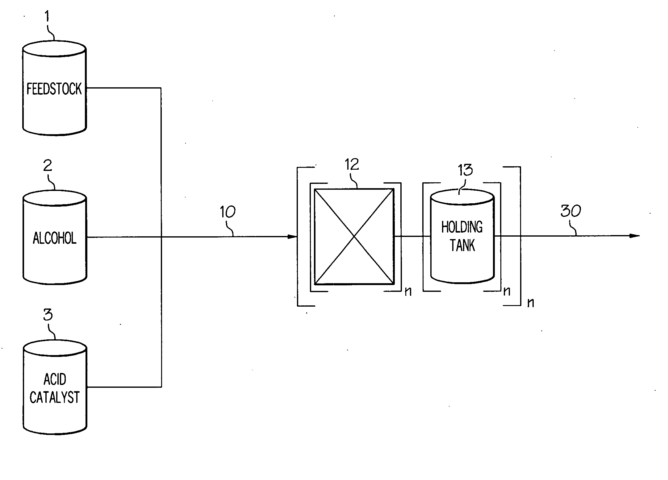
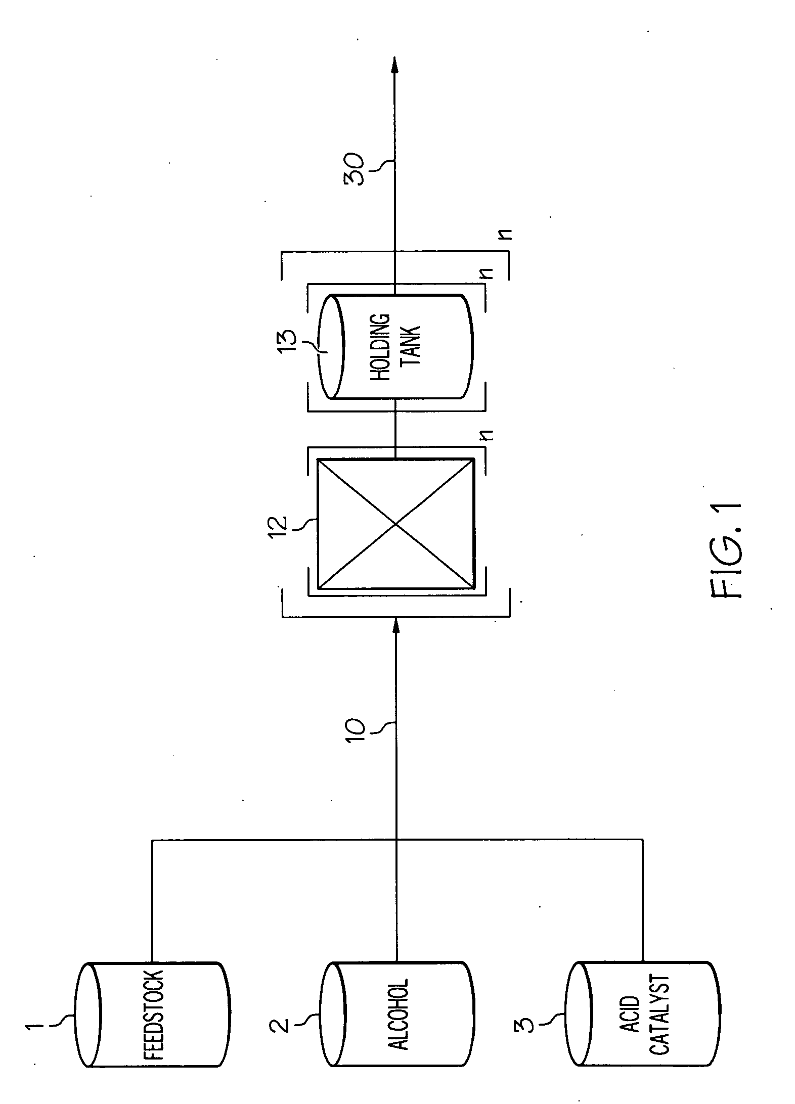
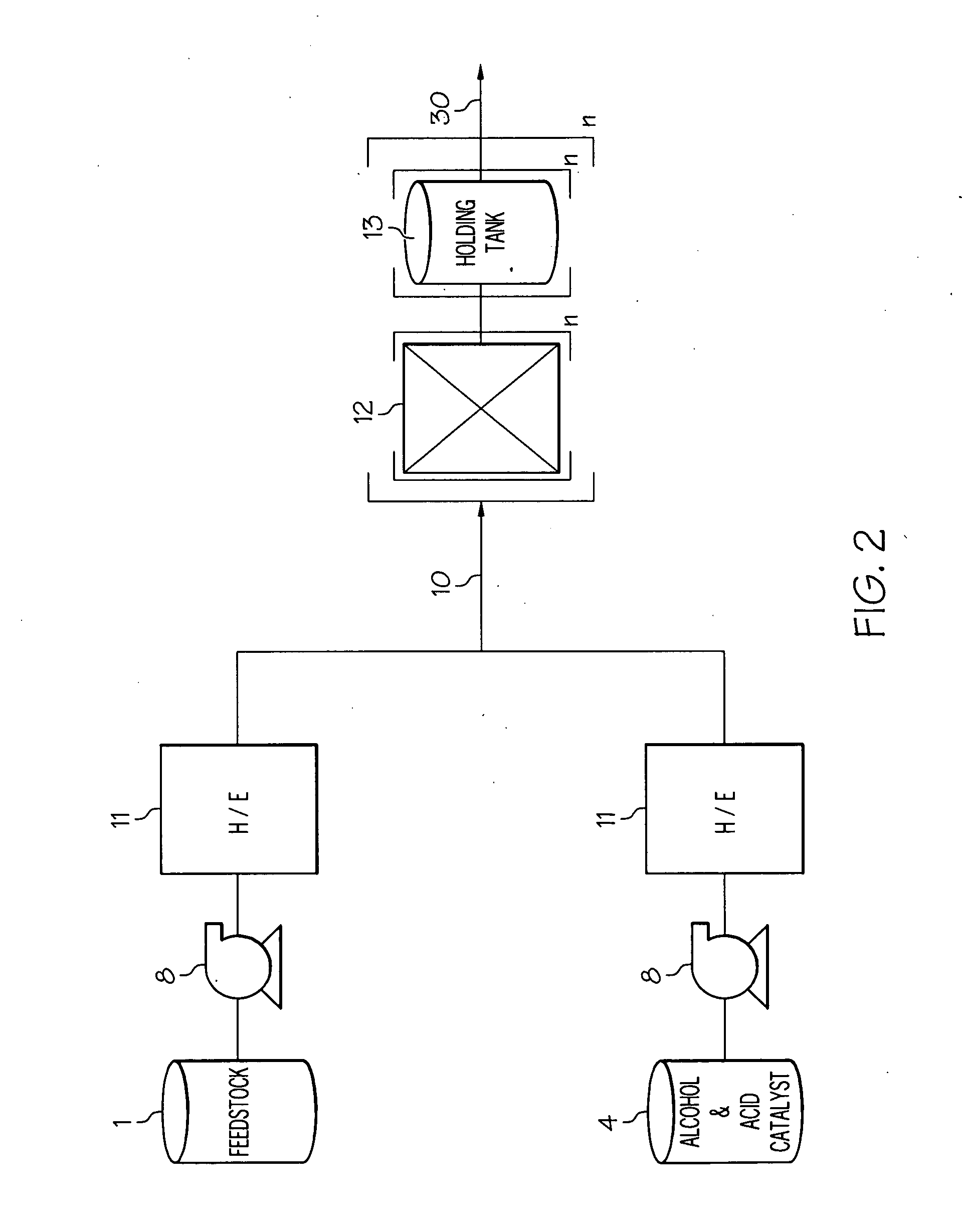
[0006]An esterification pretreatment method for reducing a high free fatty acid feedstock comprising providing a feedstock comprising a free fatty acid content in the range of 3 to 30% by weight, an alcohol and an acid catalyst. Combining the feedstock, alcohol and acid catalyst to form a reaction mixture and forcing the reaction mixture through at least two controlled flow cavitation apparatuses at a processing pressure capable of generating a hydrodynamic cavitation zone in each controlled flow cavitation apparatus, wherein a pressure differential of 50 to 250 psi across each of the controlled flow cavitation apparatuses is maintained. Holding the reaction mixture exiting the at least two controlled flow cavitation apparatuses in a holding tank for at least 10 minutes at a temperature of at least 100° C., wherein the free fatty acid content of the feedstock is reduced to less than 2% by weight by way of esterification reactions.
[000

Problems solved by technology

Feedstock sources containing a free fatty acid content higher than 3% are often unsuitable for production of biodiesel fuel due to reaction complications and low biodiesel conversion rates.
One of the complications of using a feedstock source with a high free fatty acid content is the tendency of the free fatty acids to neutralize the basic catalyst in the transesterification reaction.
Soaps act to inhibit the separation of biodiesel product from glycerin which causes a low yield of biodiesel.
This purification step then causes a lengthier production process which subsequently increases production costs.
These methods generally require a long processing time, often hours to even days, and may not provide a suitable reduction in the free fatty acid content.
The long processing times are also cost ineffective.

Method used


Image

  • Method for reducing free fatty acid content of biodiesel feedstock
  • Method for reducing free fatty acid content of biodiesel feedstock
  • Method for reducing free fatty acid content of biodiesel feedstock

Examples


example 1

[0040]A reaction mixture was prepared by combining the reactants from two holding tanks. The first holding tank contained feedstock having a free fatty acid content, palmitic acid, of 12% by weight in a mixture with degummed soybean oil. The second holding tank contained a mixture of methanol and sulfuric acid. The reaction mixture contained 1% sulfuric acid by weight of the feedstock and 96% methanol by weight of the total mixture. The mixture was passed through six cavitation apparatuses and three holding tanks in series, in an arrangement as shown in FIG. 4. More specifically, six cavitation apparatuses are arranged in series with each other while a holding tank is placed in series after every two cavitation apparatuses. The result of the run is shown in Table 1 below. All reactants were maintained at 124° C. while the initial cavitation occurred at 117° C., and the holding tanks maintained the reaction mixture at 120° C. The reaction stream moved through the apparatuses at a flo...

example 2

[0041]A reaction mixture was prepared by combining the reactants from two holding tanks. The first holding tank contained a feedstock, grease, with free fatty acid, oleic acid, at 3.8% by weight by titration according to AOCS method CA 5a-40. The second holding tank contained methanol and sulfuric acid. The reaction mixture contained 0.5% sulfuric acid by weight of the feedstock and 97% methanol by weight of the total mixture. The mixture was then run through six cavitation apparatuses and three holding tanks in series. More specifically, six cavitation apparatuses are arranged in series with each other while a holding tank is placed in series after every two cavitation apparatuses. The result of the run is shown in Table 1 below. All reactants were maintained at 119° C. while the initial cavitation occurred at 113° C., and the holding tanks maintained the reaction mixture at 110° C. The reaction stream moved through the apparatuses at a flow rate of 0.63 lpm. The orifice diameters ...

example 3

[0042]A reaction mixture was prepared by combining the reactants from two holding tanks. The first holding tank contained a feedstock of pit grease with free fatty acid content of 4.03% by weight. The second holding tank contained methanol and sulfuric acid. The reaction mixture contained 1% sulfuric acid by weight of the feedstock and 91.5% methanol by weight of the total mixture. The mixture was then run through six cavitation apparatuses and three holding tanks in series. More specifically, six cavitation apparatuses are arranged in series with each other while a holding tank is placed in series after every two cavitation apparatuses. The result of the run is shown in Table 1 below. All reactants were maintained at 122° C. while the initial cavitation occurred at 113° C., and the holding tanks maintained the reaction mixture at 114° C. The reaction stream moved through the apparatuses at a flow rate of 0.60 lpm. The orifice diameters of the six cavitation apparatuses varied from ...


PUM


Abstract

A method comprising applying controlled flow cavitation apparatuses and holding tanks to a pretreatment process in order to reduce the free fatty acid content of a biodiesel feedstock. A feedstock comprising a high content of free fatty acids can be passed through controlled flow cavitation apparatuses and holding tanks at a velocity capable of generating hydrodynamic cavitation zones and subsequent dwell times where the free fatty acid content can be reduced to below 2%.

Description

[0001]This application is a continuation-in-part of U.S. patent application Ser. No. 12 / 167,516 filed Jul. 3, 2008, which claims the benefit of U.S. Provisional Patent Application Ser. Nos. 60 / 954,659 filed Aug. 8, 2007 and 60 / 973,332 filed Sep. 18, 2007, the contents of which are incorporated herein by reference in their entirety.FIELD OF THE INVENTION[0002]The present invention relates generally to esterification of free fatty acids and more particularly to esterification of free fatty acids in controlled cavitation zones.BACKGROUND OF THE INVENTION[0003]Biodiesel fuel is produced by the transesterification of triglycerides, a source of non-free fatty acids, found in a feedstock base. A feedstock base will comprise triglycerides and “free” fatty acids, the latter of which will impede the production of biodiesel fuel. Feedstock sources containing a free fatty acid content higher than 3% are often unsuitable for production of biodiesel fuel due to reaction complications and low biod...

Claims


Application Information

Patent Timeline
IPC IPC(8): C10L1/18
CPCC10L1/026Y02E50/13C11C3/003Y02E50/10
Inventor KOZYUK, OLEG V.BRETT, MARTIN
Owner ARISDYNE STSTEMS INC
Learn More