Method and apparatus for window closing in the sliding window system

a technology for sliding windows and doors, applied in the field of window and door systems, can solve the problems of soundproofing, air tightness, tightness, insulation performance, wind pressure resistance, and the inability of the seal member to provide a high sealing effect, and achieve the effects of improving durability, improving soundproofing, and preventing damage to the seal member

Inactive Publication Date: 2009-02-12
FILOBE SYST WINDOW
View PDF6 Cites 35 Cited by
  • Summary
  • Abstract
  • Description
  • Claims
  • Application Information

AI Technical Summary

Benefits of technology

[0029]A method and apparatus for opening and closing a window in a sliding window system according to the present invention allow a movable window sash to be integrally and almost perfectly pressed against an elastic seal member interposed between the movable window sash and blank frame at any position on a rail within the blank frame, thus providing improved soundproofing, air tightness (windproofing), water tightness, insulation performance, and wind pressure resistance. The present invention also prevents damage to the seal member and each component from becoming heavily loaded, thus providing improved durability while making it easier to manage the components than components in a conventional opening and closing apparatus. The apparatus has a minimum number of components, thus offering increased productivity and constructability.
[0030]Furthermore, the at last one slant guide hole is portioned into a plurality of sections to perform a locking operation due to an elastic reaction force exerted by pressing the seal member when the movable window sash comes in contact with the seal member mounted on the blank frame, thus providing excellent sound proofing, air tightness (wind proofing), water tightness, and insulation performance without the a separate locking unit.
[0031]The present invention also provides a sliding window system with a reduced number of compact, thin components designed to provide soundproofing, air tightness (windproofing), water tightness, insulation performance, and wind pressure resistance. That is, the sliding window system has a simple, slim, large sash, thus lowering the manufacturing costs while maximizing openness of a space through the window.

Problems solved by technology

Thus, it is difficult that the typical sliding window system has soundproofing, air tightness (windproofing), water tightness, insulation performance, and wind pressure resistance.
Due to limitations of sealing techniques, such a seal member cannot provide a high sealing effect.
Further, it is difficult to maintain consistent performance due to deformation or abrasion of the seal member over time.
However, the above-mentioned window system with LS type has a drawback that it is dynamically difficult for components related to the roller on the lower portion of the movable window sash to lift the heavy-weight of the movable window sash due to the concentration load that is applied to the roller when the movable window sash is opened or closed.
Such a drawback imposes a limitation on the size of an applicable movable window sash because load applied by an excessively large movable window sash frame and a glass pane becomes burdensome.
As described above with reference to FIGS. 4 and 5, another drawback of the LS type window system is that it is difficult to provide a perfect seal between each corner of the movable window sash and the blank frame because top, bottom, and side seal members mounted to one movable window sash effect a seal in different directions using different techniques.
In addition, it is also difficult to create a perfect seal between the upper portion of the movable window sash and the top guide, since sealing force generated when the top seal member 3u is elastically contacted on the top guide 1a is lowered.
In particular, it is difficult to prevent heat from being transferred from an exterior to an interior through the top guide 1a.
Another drawback is that transverse friction pressure is applied to the rubber buffer while the sliding window is closed, so as to created a seal between the rubber buffer and the guide member when the sliding window sash and guide member further move toward the blank frame (in a closing direction) in a state that the rubber buffer and the guide member are contacted on each other.
The transverse friction pressure degrades durability and lifespan of a rubber seal member.
Yet another drawback lies in a technical configuration and operation of a movable member mounted on a roller part of the sliding window sash as illustrated in FIGS. 9 to 12 in the above-cited reference.
However, actually, in a case that a user in the house opens / closes the window, that is, the user holds a handle and pushes the sliding window sash backwards, at the same time the user transversely slides the sliding window, the window system disclosed in the above-cited reference has a problem in that contact friction between the sliding window sash and the seal member occurs due to the absence of a means for actively controlling a gap between the roller and the rail.
Thus, another problem of the conventional window system is that front and rear gaps between a top guide of the blank frame and the upper portion of the sliding window sash cause the upper portion of the sliding window sash to rattle and move back and forth.
However, the conventional sliding window system with the movable window sash 4 mounted on the cantilever arm 4b has a limitation on the size of the movable window sash 4 due to load.
Therefore, productivity becomes degraded and the manufacturing cost becomes increased.
Another drawback is that the upper portion of the movable window sash is more likely to move back and forth due to wind pressure when high wind blows in a state that the movable window sash is not completely closed, making a user feel uneasy about the movement of the window.

Method used


Image

  • Method and apparatus for window closing in the sliding window system
  • Method and apparatus for window closing in the sliding window system
  • Method and apparatus for window closing in the sliding window system

Examples


first embodiment

[0074]FIG. 14 illustrates the overall configuration of a sliding window system having an opening / closing device according to a preferred embodiment of the present invention (hereinafter referred to as the “first embodiment”). FIGS. 15 and 16 are simplified perspective views illustrating the states of the opening / closing device 50 shown in FIG. 14 before and after rotation.

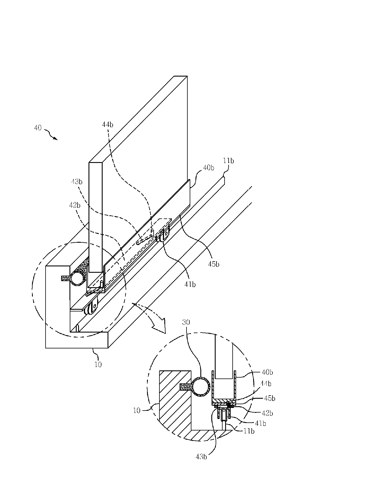
[0075]Referring to FIGS. 15 and 16, the opening / closing device 50 includes a rotating axis member 50c that has a rotary handle 50h and that is mounted along a longitudinal direction of the side frame 40s, connecting rods 52b and 52a that are respectively linked to the top plate 42b of the roller assembly 41b and 42b and the bottom plate 42a of the rail guide assembly 41a and 42a and transform rotational motion into reciprocating motion, and first and second rotating end members 51a and 51b, each of which having one end fixed to either top or bottom of the rotary axis member 50c and the other end linked to either of...

second embodiment

[0093]A sliding window system including an opening / closing device with a different structure than the opening / closing device 50 described with reference to FIGS. 14 to 26 according to another embodiment of the present invention (hereinafter referred to as the “second embodiment”) will now be described with reference to FIGS. 27 to 40. FIG. 27 illustrates the overall configuration of a sliding window system having a slidable opening / closing system 150. FIGS. 28 and 29 are perspective view illustrating the configuration and operation of the sliding opening / closing device 150 and an exploded enlarged perspective view of a main portion of the slidable opening / closing device 150.

[0094]More specifically, referring to FIGS. 27 to 40, the slidable opening / closing device 150 according to the second embodiment includes a side slide bar 150c mounted along a side frame of the movable window sash 40 to allow up and down movement, a rotary handle 150h applying a force causing the side slide bar 1...


PUM

PropertyMeasurementUnit
timeaaaaaaaaaa
timeaaaaaaaaaa
lengthaaaaaaaaaa

Abstract

Provided are an apparatus and method for opening and closing a window by slidably moving a movable window sash or door (hereinafter collectively called a ‘movable window sash’) with respect to a fixed window sash or door (hereinafter collectively called a ‘fixed window sash’). The apparatus is designed such that the movable window sash cannot only slide along a rail mounted within a blank frame but also be separated from a roller to move back and forth from any position on a rail toward the blank frame or the fixed window sash in a perpendicular direction with respect to a length direction of the rail, thus allowing the entire seal member interposed between either the blank frame or the fixed window sash and the movable window sash to be uniformly pressed in the perpendicular direction. Thus, excellent soundproofing, air tightness (windproofing), water tightness, insulation performance, and wind pressure resistance can be provided. Furthermore, the sliding window system has a simplified opening/closing structure and a minimum number of components, and low manufacturing cost.

Description

TECHNICAL FIELD[0001]The present invention relates to a window and door system such as sliding doors or windows, and more particularly, to a method and apparatus for opening / closing a window in a sliding window system by slidably moving a movable window or door (hereinafter collectively called ‘movable window’) with respect to a fixed window or door (hereinafter collectively called ‘fixed window’).BACKGROUND ART[0002]FIGS. 1 to 3 illustrate a typical configuration of a sliding window system such as sliding windows or doors. Referring to FIGS. 1 to 3, the sliding window system includes a movable window sash 4 holding a glass pane, etc., and a blank frame 1 that has top and bottom rails 1a and 1b for slidably guiding the moving window sash 4 and that is mounted in a wall of a building. A roller 4a is attached to the bottom rail 1b so that the movable window sash 4 can smoothly move along the rail 1b. The movable window sash 4 holding the glass pane or a panel is mounted in the blank f...

Claims


Application Information

Patent Timeline
Patent Type & Authority Applications(United States)
IPC IPC(8): E05F11/02E06B3/46
CPCE05D15/1042E06B3/4627E05Y2900/132E05Y2900/148E06B7/23E05D15/10E05D2015/1039E05F11/145E05Y2201/604E05Y2201/62E05Y2201/706E05D15/06E05D15/40E06B7/16E06B7/18
Inventor LEE, KWANG-SEOK
Owner FILOBE SYST WINDOW
Why Eureka
Try Eureka