
Plasma ignition burner

a technology of ignition burner and plasma, which is applied in the direction of burners, plasma techniques, combustion types, etc., can solve the problems of clinkering of pulverized coal, the guide plate cannot completely deflect air flow, and cannot be used further, so as to relieve the problem of clinkering

Inactive Publication Date: 2009-02-12
YANTAI LONGYUAN POWER TECH
View PDF3 Cites 17 Cited by
  • Summary
  • Abstract
  • Description
  • Claims
  • Application Information

AI Technical Summary

Benefits of technology

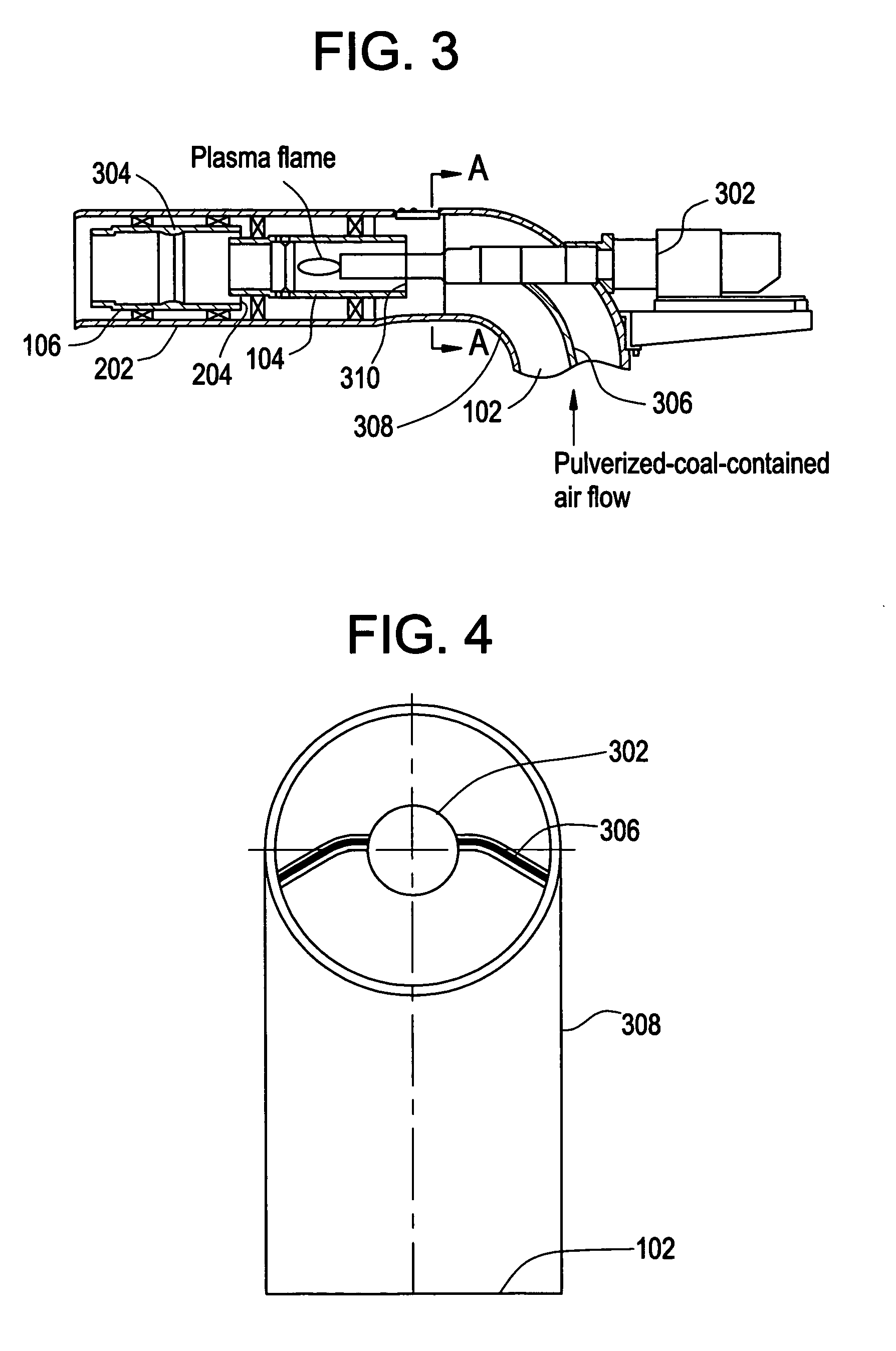
[0010]Therefore, an object of the present invention is to provide a plasma generator which can relieve the problem of clinkering. It can be seen from the above description of the prior art, the fact that there exists an angle between the inserting direction of the plasma generator (that is, the direction of the plasma flame) and the direction of the pulverized-coal-contained air flow is a reason of the clinkering problem. Therefore, with respect to the above object, the gist of the present invention is to rearrange the pulverized-coal-contained air flow inlet and the plasma generator, so as to make the direction along which the pulverized-coal-contained air flow enters into the first stage burner barrel consistent with the direction of the plasma flame.

Problems solved by technology

This is also a hierarchical ignition manner, but since the temperature in the precombustion chamber is too high, the pulverized coal easily clinkers inside and therefore can not be used further.
However, the guide plate can not deflect the air flow completely due to the limitation of the space.
Since the two air flows can not be absolutely parallel, the entering air flow will blow the plasma flame (or the former stage flame) deflected, which causes the temperature of the barrel wall increasing and the pulverized coal clinkering.
In addition, in this technology, because the pulverized-coal-contained air flow and the air flow both enters in the direction perpendicular to the burner barrels, on the section plane perpendicular to the burner barrels, the concentration of the pulverized coal and the velocity of the air flow, et al. are not uniform, thereby affecting the burning quality.

Method used


Image

  • Plasma ignition burner
  • Plasma ignition burner
  • Plasma ignition burner

Examples


first embodiment

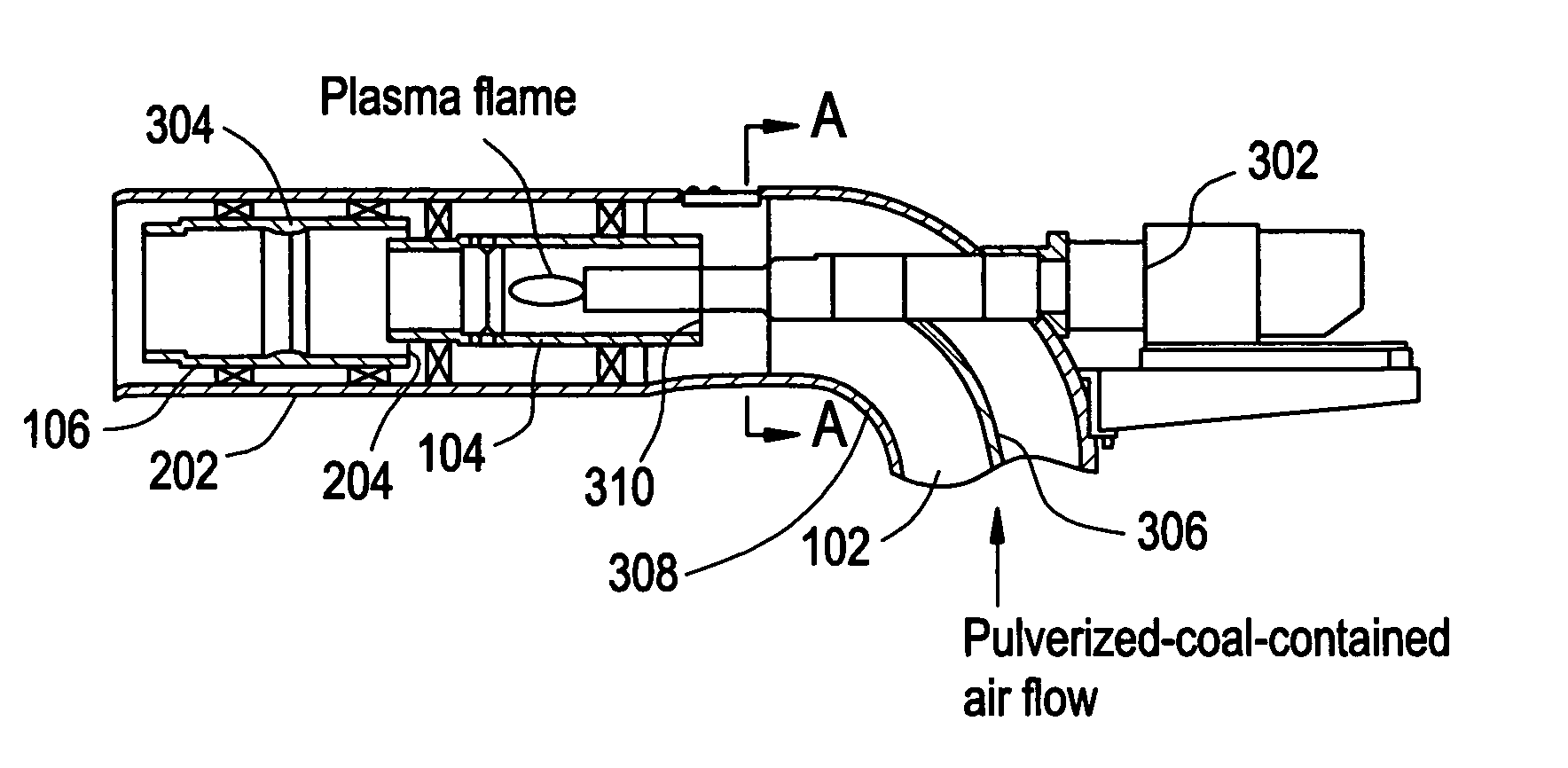
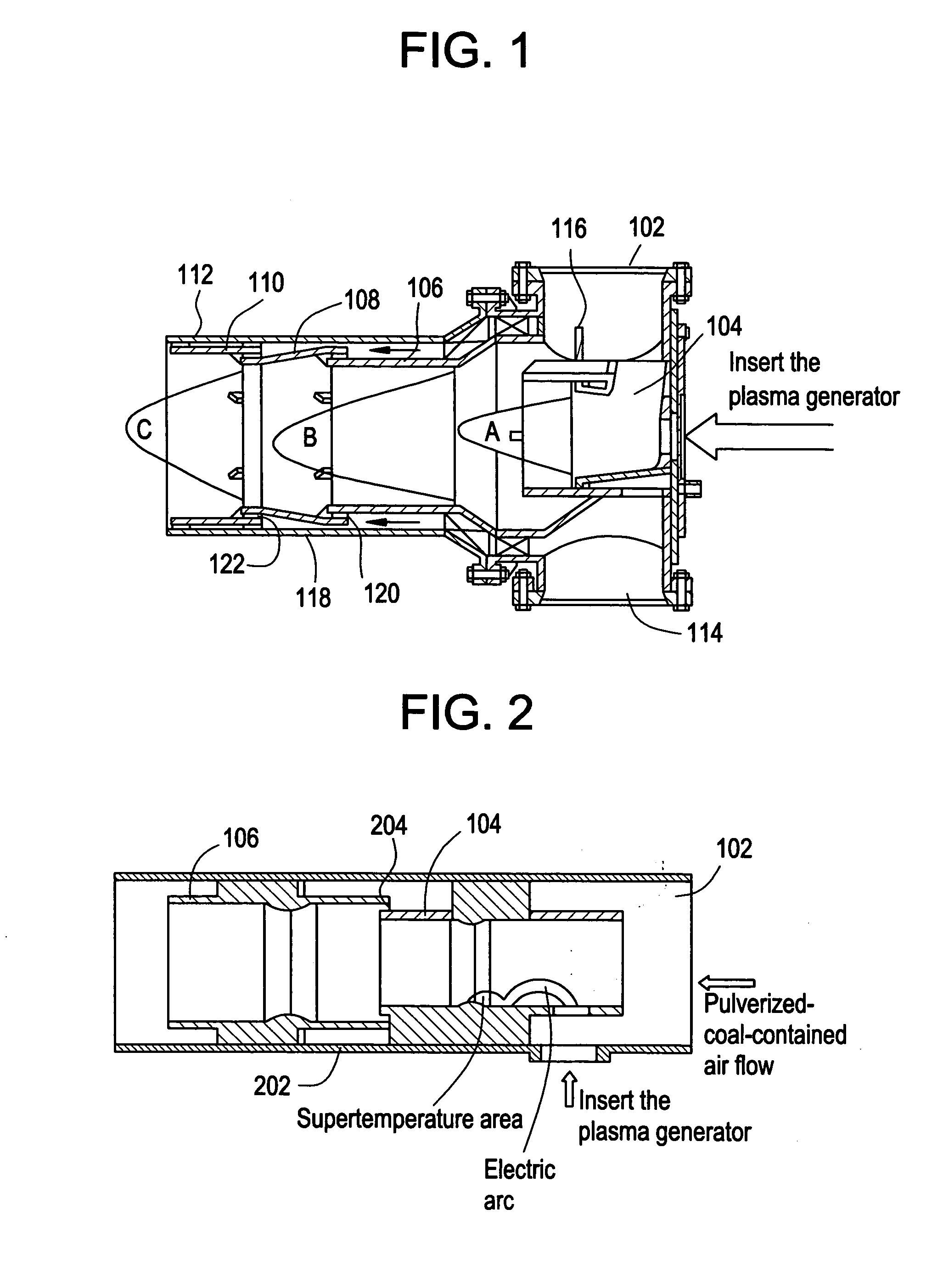
[0020]FIG. 3 illustrates the partial sectional view schematically illustrating the plasma ignition burner according to the first aspect of the present invention. To be concise, this figure also only illustrates the pulverized-coal-contained air flow inlet 102, the first stage burner barrel 104 and the second stage burner barrel 106 similar to those in FIG. 2. Since the structure of the multi-stage structure of burner barrels has been described as above, it is not repeated here. What should be noted is that, as described in the part “BACKGRAOUND ART”, the stage number of the burner barrels into which the pulverized-coal-contained air flow enters, the stage number of the burner barrel into which the air directly enters and the total stage number of the burner barrels are not limited and can be determined depending on power request and the size of the space. The total number of the stages may be from two stages to three, four or more stages and the air flow as shown in FIG. 1 may be al...

second embodiment

[0033]In addition, for those old type burners which have been amounted on the spot, a convenient and low-cost reconstructing means can be provided by using the above-described second embodiment, so that the present invention can be applied.

[0034]For example, the whirling type pulverized coal burner adopted by many burning coal firepower electricity generator has a central barrel and the mixture of the pulverized coal and the air is sent into the hearth from the external of the central barrel. For example, LNASB axial swirl pulverized coal burner (refer to FIG. 6) developed by Mitsui Babcock Energy Ltd in the eighties of 20th century adopts this kind of structure. In this structure, the oil gun is inserted into the central barrel 602 and the pulverized coal sent into the hearth from the external of the central barrel is ignited by the flame of the oil gun. For this kind of burner, if the reconstruction of the plasma ignition technology is to be directly performed, it is necessary to ...


PUM


Abstract

A plasma ignition burner. The plasma ignition burner has at least two stages of burner barrels and a plasma generator for igniting the pulverized coal in a first stage burner barrel of the at least two stages of burner barrels. The burning flame of the former stage burner barrel ignites the pulverized coal in the next stage burner barrel, or further burns with the supplemented air in the next stage burner barrel. The axial direction of said plasma generator is parallel to the direction along which the pulverized-coal-contained air flow enters into the first stage burner barrel and at the same time, parallel to the axis of the burner barrels.

Description

TECHNICAL FIELD[0001]The present invention relates to pulverized coal burning technical field, and particular to a plasma ignition burner.BACKGROUND ART[0002]Coal fired power generation is a main electricity generation manner adopted by different countries at present. Ignition is a main aspect of the burning process of the boiler. With the enlargement of the capacity of the boiler, how to accomplish the starting process of the boiler rapidly and economically becomes an important problem to be imminently solved.[0003]Plasma ignition technology has been developed recently to replace the oil ignition manner which consumes a lot of burning oil.[0004]In order to be able to ignite inferior coal, the conventional plasma igniting system adopts the so-called “precombustion chamber” technology. The precombustion chamber is constructed to keep the temperature of the burner barrel, normally by attaching a layer of fire-resistant material to the internal of the firebox. The chamber wall of the p...

Claims


Application Information

Patent Timeline
IPC IPC(8): F23D1/00
CPCF23D1/00F23D2207/00F23D2201/20F23D2201/10F23Q13/00H05H1/26
Inventor LIU, PENGZHANG, XIAOYONGQIAN, YINGJIEWANG, XINGUANGYU, WENBOCAI, FEIMIAO, YUWANGNIU, TAOWANG, YUPENG
Owner YANTAI LONGYUAN POWER TECH
Learn More