Permanent Magnet or Permanent Magnet Array having Uniform Flux Density

a permanent magnet and flux density technology, applied in the direction of magnets, magnetic bearings, magnetic bodies, etc., can solve the problems of inconsistency in magnetic flux field density, undesirable magnetic effect of non-uniform flux field density, and rare, if ever, to achieve completely uniform field densities. , to achieve the effect of increasing the density of magnetic flux field

Inactive Publication Date: 2009-02-12
KIPP RONALD +2
View PDF12 Cites 25 Cited by
  • Summary
  • Abstract
  • Description
  • Claims
  • Application Information

AI Technical Summary

Benefits of technology

[0016]It has been recognized that it would be advantageous to develop a device for uniformly distributing the magnetic flux field emanating from a magnet. It has also been recognized that it would be advantageous to develop a device for concentrating, or increasing the density of magnetic flux field emanating from a magnet.
[0017]The invention provides a permanent magnet device including an axially polarized permanent annular magnet having two opposite faces. Additionally, a magnetically conductive annular faceplate is disposed on each of the opposite faces of the permanent magnet. Each faceplate is sized, shaped and oriented to equally distribute the flux lines emanating from the permanent magnet, and to increase the density of the magnetic flux field of the permanent magnet.

Problems solved by technology

The precision ceramic magnets that are used in these applications are manufactured to very high standards, but rarely, if ever, do they reach completely uniform field densities.
Unfortunately, cost, efficiency and technology limitations in manufacturing permanent magnets result in magnetic flux field density inconsistencies.
The similarity in the calculated magnet flux density due to physical and / or chemical imbalance shown in FIG. 3, and the empirically measured values shown in FIG. 4 is more than coincidental, and illustrates that even slight variations within the chemical uniformity, magnet activation process, and / or dimensional variations of these ceramic magnets can lead to the undesirable magnetic effect of non-uniform flux field density.
It will be further appreciated that magnetic offsets from the true centerline of these components can introduce unbalance within the system, place the support system at risk, and burden the control system with unnecessary and unwanted correction factors.
If a magnetic flux field imbalance within any one of the system components introduces a physical magnetic offset of greater than 0.010″, then the levitation mechanism will be inoperative and the entire magnetic support mechanism will be in jeopardy.
Additionally, the magnetic unbalance of all of the interacting components (rotor and stator) within the system can have a combined negative effect on the overall system performance.

Method used


Image

  • Permanent Magnet or Permanent Magnet Array having Uniform Flux Density
  • Permanent Magnet or Permanent Magnet Array having Uniform Flux Density
  • Permanent Magnet or Permanent Magnet Array having Uniform Flux Density

Examples


Embodiment Construction

[0045]Reference will now be made to the exemplary embodiments illustrated in the drawings, and specific language will be used herein to describe the same. It will nevertheless be understood that no limitation of the scope of the invention is thereby intended. Alterations and further modifications of the inventive features illustrated herein, and additional applications of the principles of the inventions as illustrated herein, which would occur to one skilled in the relevant art and having possession of this disclosure, are to be considered within the scope of the invention.

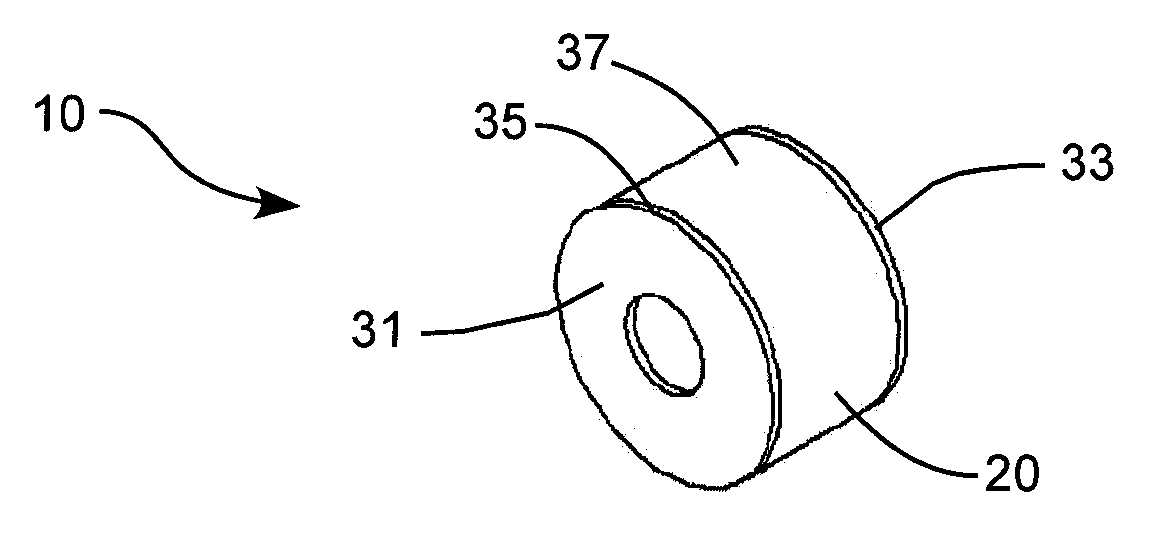
[0046]The embodiments of the present invention described herein generally provide for a magnetic device that evenly distributes and concentrates the magnetic flux emanating from a magnet. It will be appreciated that magnetic flux or flux lines propagating through a soft magnetic medium, such as iron or steel volumetrically distribute themselves along the desired pathway. The path for these flux lines is generally...


PUM

PropertyMeasurementUnit
magnetically conductiveaaaaaaaaaa
magnetic fluxaaaaaaaaaa
magnetic field flux densityaaaaaaaaaa

Abstract

A permanent magnet device includes a polarized permanent annular magnet having two oppositely charged poles faces. A magnetically conductive faceplate is disposed on each of the opposite pole faces of the permanent magnet. Each faceplate is sized, shaped and oriented to equally distribute the flux lines emanating from the permanent magnet, and to increase or concentrate the density of the magnetic flux field of a permanent magnet or permanent magnet device.

Description

PRIORITY CLAIM[0001]Benefit is claimed of U.S. Provisional Patent Application No. 60 / 959,162, filed Jul. 9, 2007, which is herein incorporated by reference in its entirety for all purposes.GOVERNMENT RIGHTS[0002]This invention was made with government support under Grant No. NIH HL64378 and Grant No. NIH HL077085 awarded by the National Institute of Health. The U.S. Government has certain rights in the invention.BACKGROUND OF THE INVENTION[0003]1. Field of the Invention[0004]The present invention generally relates to a permanent magnet apparatus, such as radial and axial permanent magnetic bearings, brush less motors, and to magnetic position sensing that requires a uniform distribution of magnetic flux.[0005]2. Related Art[0006]Precision ceramic permanent magnets are manufactured in a multitude of forms throughout the world to fulfill the needs of various applications, such as permanent magnetic bearings, brushless motors, electromagnetic actuators, speakers, microphones, and a var...

Claims


Application Information

Patent Timeline
Patent Type & Authority Applications(United States)
IPC IPC(8): H01F7/02H02K21/16
CPCF16C32/0408H01F1/14708H02K1/2713H01F7/0236H01F41/0253H01F1/14766
Inventor KIPP, RONALDDAY, STEVEN W.OLSEN, DON B.
Owner KIPP RONALD
Why Eureka
Try Eureka