Vapor chamber structure and method for manufacturing the same

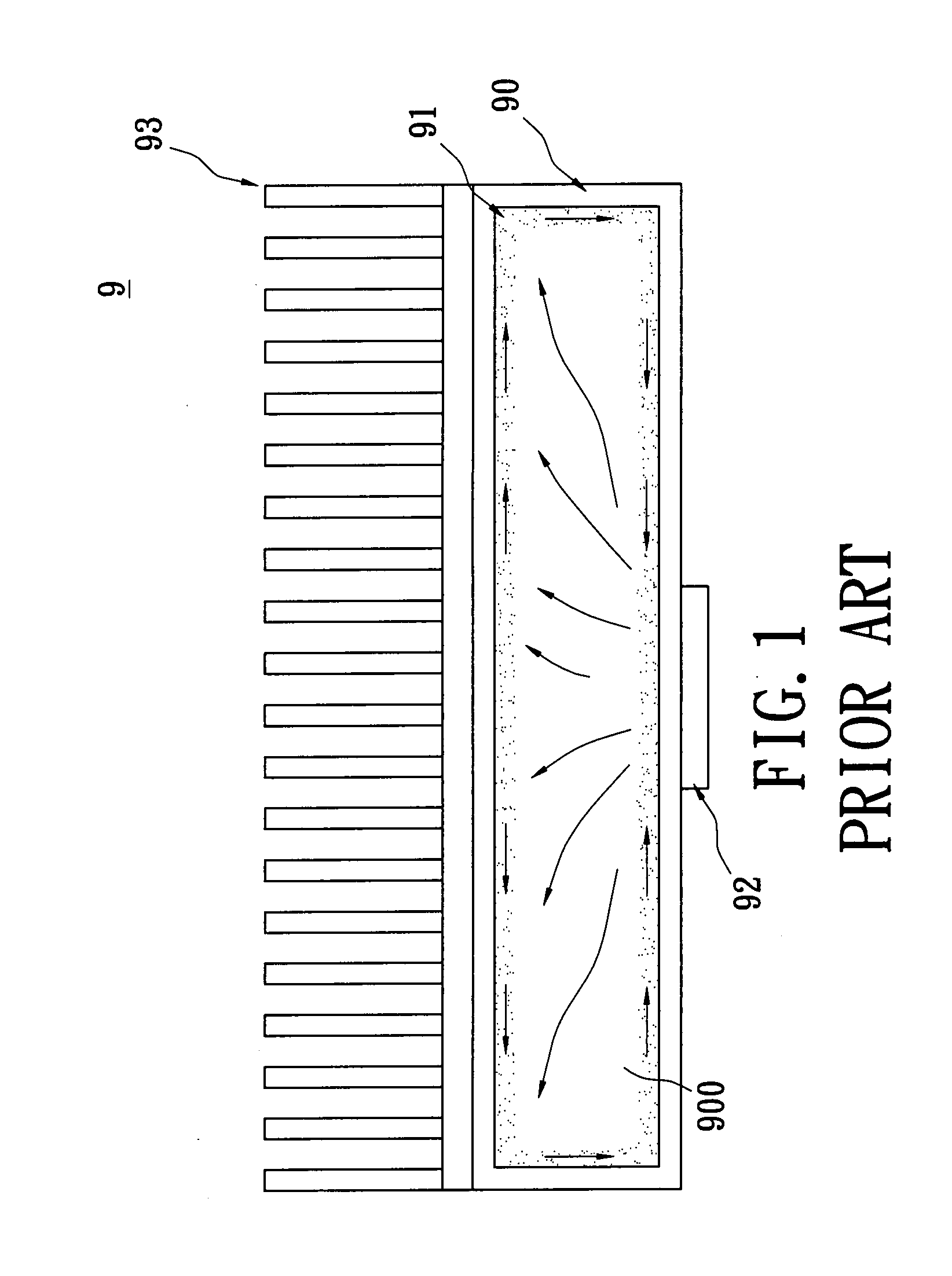
a technology of vapor chamber and working fluid, which is applied in the direction of indirect heat exchangers, semiconductor/solid-state device details, lighting and heating apparatus, etc., can solve the problems of limited backflow efficiency (ability to return the working fluid to the evaporator portion of the vapor chamber) and the major obstacle of cooling or heat removal. to meet the higher cooling requirements of newer electronic devices. , to achieve the effect of improving the structural strength

Inactive Publication Date: 2009-02-12
THERMAL TECH
View PDF0 Cites 108 Cited by
  • Summary
  • Abstract
  • Description
  • Claims
  • Application Information

AI Technical Summary

Benefits of technology

[0012]One particular aspect of the present invention is to provide a vapor chamber structure and a method for manufacturing the same. The ...

Problems solved by technology

Cooling or heat removal has been one of the major obstacles of the electronic industry.
However, this conductive heat transfer through solid materials is generally insufficient to meet the highe...

Method used


Image

  • Vapor chamber structure and method for manufacturing the same
  • Vapor chamber structure and method for manufacturing the same
  • Vapor chamber structure and method for manufacturing the same

Examples


Embodiment Construction

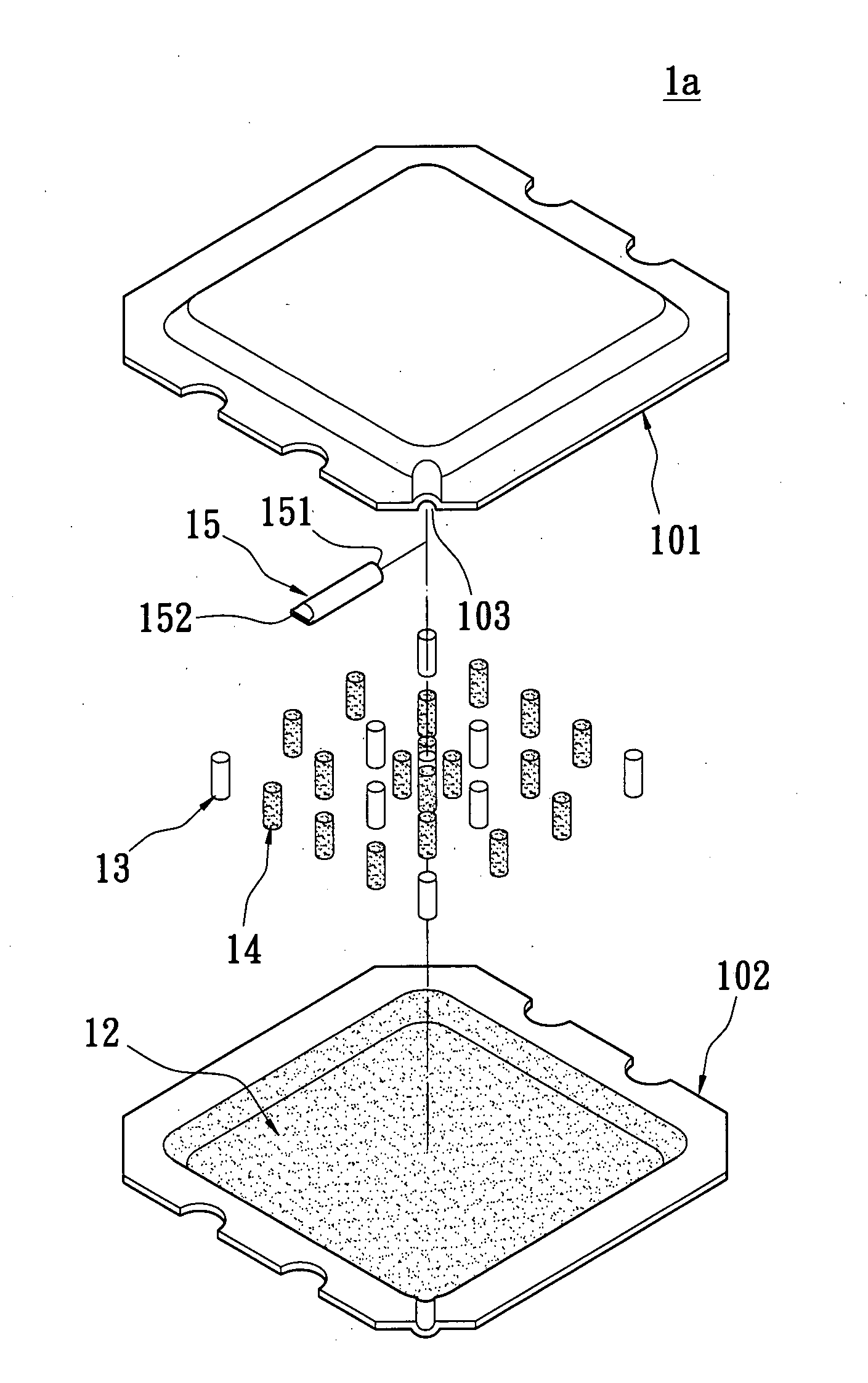
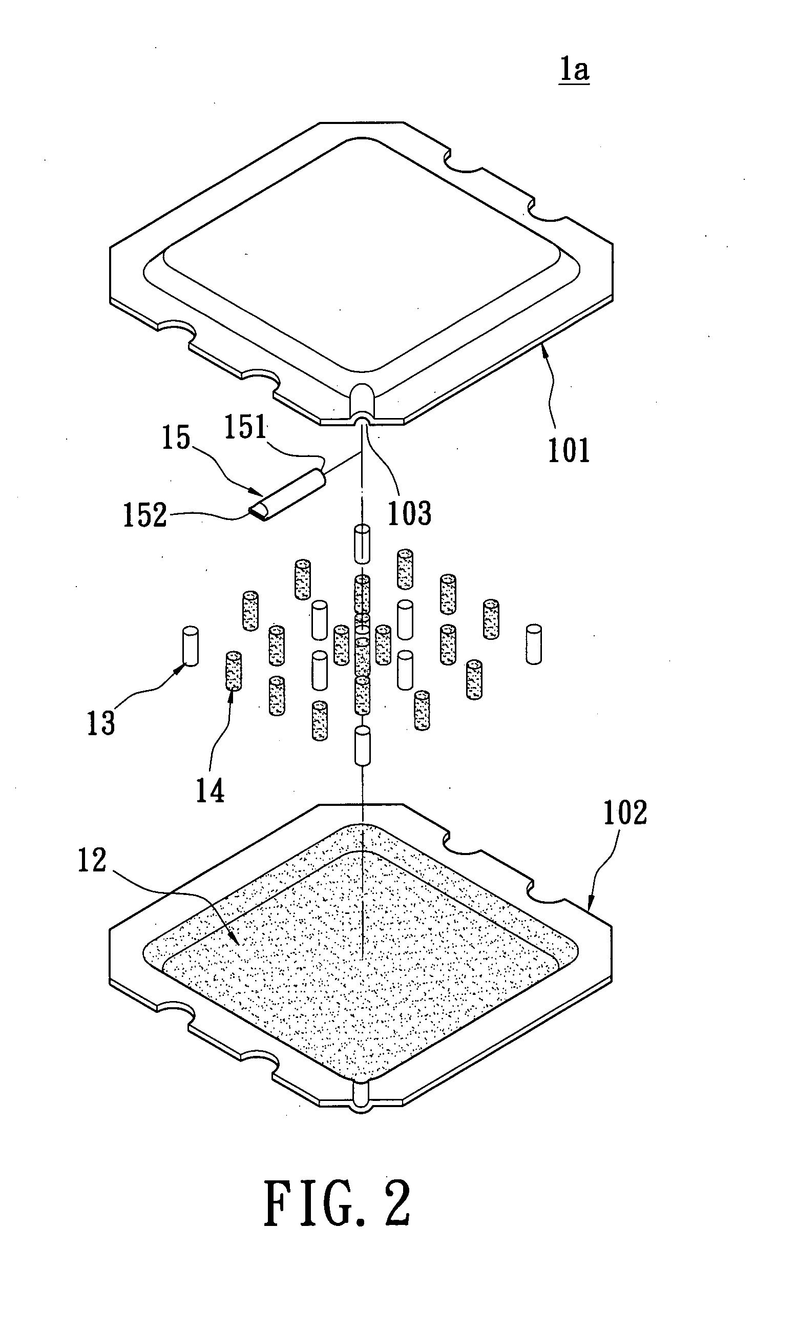
[0076]Referring to FIGS. 2 to 5, the first embodiment of the present invention provides a vapor chamber structure 1a, comprising: a casing 10, a working fluid 20, a wick layer 12, and one or more structure strengthening bodies 13.

[0077]The casing 10 has an airtight vacuum chamber 100, and the working fluid 20 is filled into the airtight vacuum chamber 100. The casing 10 is composed of one or more upper casings 101 and one or more lower casings 102 that mate with the upper casings 101. Moreover, the casing 10 has contact surfaces between the upper casings 101 and the lower casings 102. The contact surfaces have a predetermined width W, in order to assemble the upper casings 101 and the lower casings 102 easily.

[0078]Furthermore, the vapor chamber structure further comprises one or more filling pipes 15 communicated with the airtight vacuum chamber 100 via a joint opening 103 of the casing 10. The filling pipe 15 has an opening side 151 formed on one side thereof and a closed side 152...


PUM

PropertyMeasurementUnit
Lengthaaaaaaaaaa
Thicknessaaaaaaaaaa
Diameteraaaaaaaaaa

Abstract

A vapor chamber structure includes a casing, a working fluid, a wick layer, a plurality of structure strengthening bodies, and a plurality of backflow accelerating bodies. The casing has an airtight vacuum chamber. The working fluid is filled into the airtight vacuum chamber. The wick layer is formed on a surface of the airtight vacuum chamber. The structure strengthening bodies are respectively arranged in the airtight vacuum chamber for supporting the casing. The backflow accelerating bodies are respectively arranged in the airtight vacuum chamber for increasing the backflow velocity of the working fluid. Therefore, the present invention can maintain the completeness of the vapor chamber structure and increase the backflow velocity of the working fluid due to the match of the structure strengthening bodies and backflow accelerating bodies. Because the backflow velocity of the working fluid is increased, the heat-transmitting efficiency is increased.

Description

BACKGROUND OF THE INVENTION[0001]1. Field of the Invention[0002]The present invention relates to a vapor chamber structure and a method for manufacturing the same, and particularly relates to a vapor chamber structure having a structure strengthening function and a method for manufacturing the same.[0003]2. Description of the Related Art[0004]Cooling or heat removal has been one of the major obstacles of the electronic industry. The heat dissipation increases with the scale of integration, the demand for higher performance, and the increase of multi-functional applications. The development of high performance heat transfer devices becomes one of the major development efforts of the industry.[0005]A heat sink is often used for removing the heat from the device or from the system to the ambient. The performance of a heat sink is characterized by the thermal resistance with a lower value representing a higher performance level. This thermal resistance generally consists of the heat-spr...

Claims


Application Information

Patent Timeline
IPC IPC(8): H05K7/20B21D53/02
CPCB22F3/20B22F3/225B22F7/062F28D15/0233F28D15/0283F28D15/046Y10T29/49353F28F2215/06F28F2225/04F28F2240/00H01L2924/0002H01L23/427H01L2924/00
Inventor HOFFMAN, PAULTANDON, RAJIVREMSBURG, RALPHSEMENIC, TADEJHONG, CHU-WANLEE, CHE-YIN
Owner THERMAL TECH
Why Eureka
Try Eureka