Variable equalizer apparatus

a variable equalizer and equalizer technology, applied in the field of variable equalizer apparatuses, can solve the problems of amplifiers generating additional noise, their circuitry, and contributing additional distortions

Inactive Publication Date: 2009-02-12
BROADBAND INT
View PDF17 Cites 9 Cited by
  • Summary
  • Abstract
  • Description
  • Claims
  • Application Information

AI Technical Summary

Benefits of technology

[0016]Exemplary embodiments of the present invention can include a make before break motherboard that plugs into the same location as a common equalizer. A motherboard embodying the present invention can allow a technician to adjust the system equalization when either a standard equalizer, fixed variable resistance equalizer with a selective jumper or the variable potentiometer with an adjustable resistance without creating a system outage.

Problems solved by technology

Amplifiers generate additional noise at various points in their circuitry.
As amplifiers are not perfectly linear they will also contribute additional distortions each time a signal is amplified.
Due to the inherent contributions of noise and distortion (e.g., nonlinearity), the signal can only be amplified a certain number of times before the change in the signal, as compared to the signal provided at the headend, becomes unacceptable.
The cascade effects of the amplifiers (e.g., net distortion introduce into the signal) typically results in a limited number of amplifiers in a continuous cascade.
The limiting factors may include the type of modulation, total number of channels and desired performance at the end of the cascade.
For example, changing the fixed value equalizer circuits commonly results in a 1-2 minute outage.
The correct value equalizer to balance the system to designed specifications may vary when the temperature changes from 100 degree F. to 0 degrees F. Variable equalizers have been attempted in the past, but with historically very little success due to the overall concept that one equalizer can range the entire 20 dB equalization range.

Method used


Image

  • Variable equalizer apparatus
  • Variable equalizer apparatus
  • Variable equalizer apparatus

Examples


Embodiment Construction

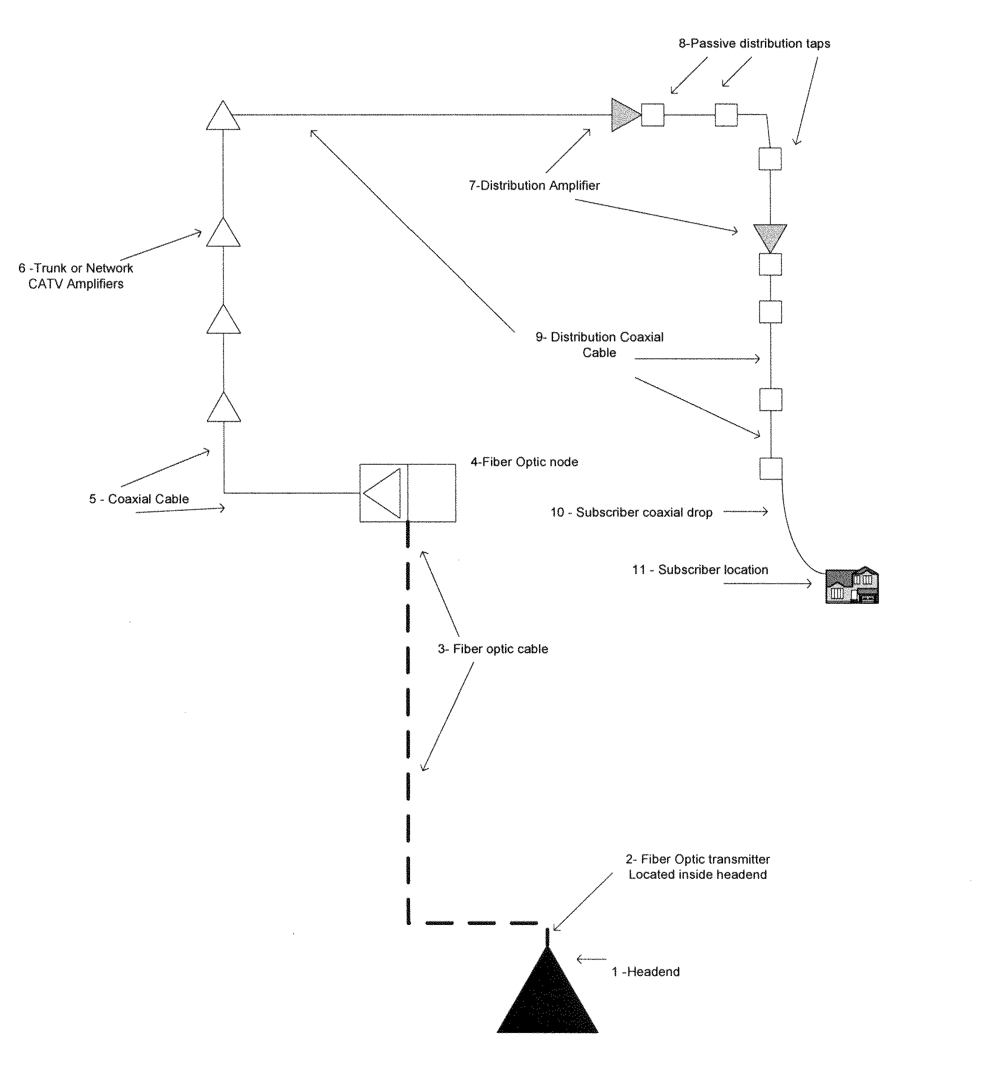
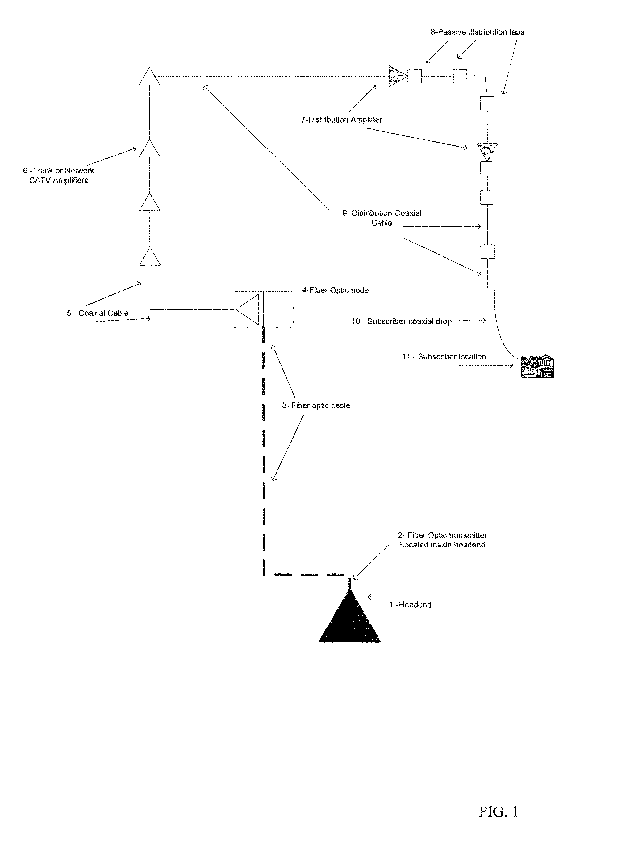
[0027]FIG. 1 is a schematic drawing of a typical coaxial cable based CATV system. FIG. 1 can represent a typical cable television system that is currently deployed to service cable television subscribers. In the illustrative example shown in FIG. 1, forward signals originate at the headend facility 1 that supplies forward signals to the optical transmitter 2. The optical transmitter transmits the CATV signal to the optical node 4 over the fiber optic cable 3. The optical node 4 also transmits return path signals to the headend optical receiver. A separate optical receiver (not shown) can be located in the headend 1 to receive and process the return path signals form the optical node 4.

[0028]The optical node 4 processes the optical signal and can provide a standard RF output signal. The standard RF output signal is then provided to and carried over the coaxial cable 5 to CATV trunk or Network amplifiers 6. Depending upon the network architecture, the Trunk or Network amplifiers 6 can...


PUM


Abstract

A variable equalizer apparatus for forward and / or reverse equalizers in an amplifier. The system can include a structure to allow continuous contact of the signal flow as an equalizer is removed; jumpers with fixed resistors and associated capacitors and inductors to produce a variable range over many different values; and / or variable resistance potentiometers with fixed resistors and associated capacitors and inductors to produce a variable range over separate value equalizers.

Description

[0001]This application claim priority to provisional application No. 60 / 929,168 filed Jun. 15, 2007.BACKGROUND OF THE INVENTION[0002]Cable Television networks were originally designed for delivering analog broadcast signals to multiple subscribers. As other signals have been added to the cable system, they have been supported by being transmitted through low noise amplifiers. These amplifiers have progressed in development from 300 MHz to 1 GHz. The analog signals have been joined with digitally compressed video signals, high speed data network signals and digital telephone signals to provide a multiple source of telecommunications to the end user. System architectures have evolved from simple coaxial based transport to advanced architectures that include fiber optic cable and other advanced transmission techniques.[0003]The signals originate at the headend facility and are processed to a broadband output signal. Reception of these signals may include satellites, off-air and direct ...

Claims


Application Information

Patent Timeline
Patent Type & Authority Applications(United States)
IPC IPC(8): H03H7/30
CPCH03F3/62H04L25/03885H03F2200/63
Inventor PEREZ, EDWARDWALLIS, DAVID
Owner BROADBAND INT
Why Eureka
Try Eureka