
Multiple camera imaging method and system for detecting concealed objects

a multi-camera imaging and concealed object technology, applied in the field of security systems, can solve the problems of not only exposing security personnel to danger, but also other individuals, and achieve the effect of convenient operation and synchronization for security personnel

Inactive Publication Date: 2009-02-12
MICROSEMI
View PDF5 Cites 31 Cited by
  • Summary
  • Abstract
  • Description
  • Claims
  • Application Information

AI Technical Summary

Benefits of technology

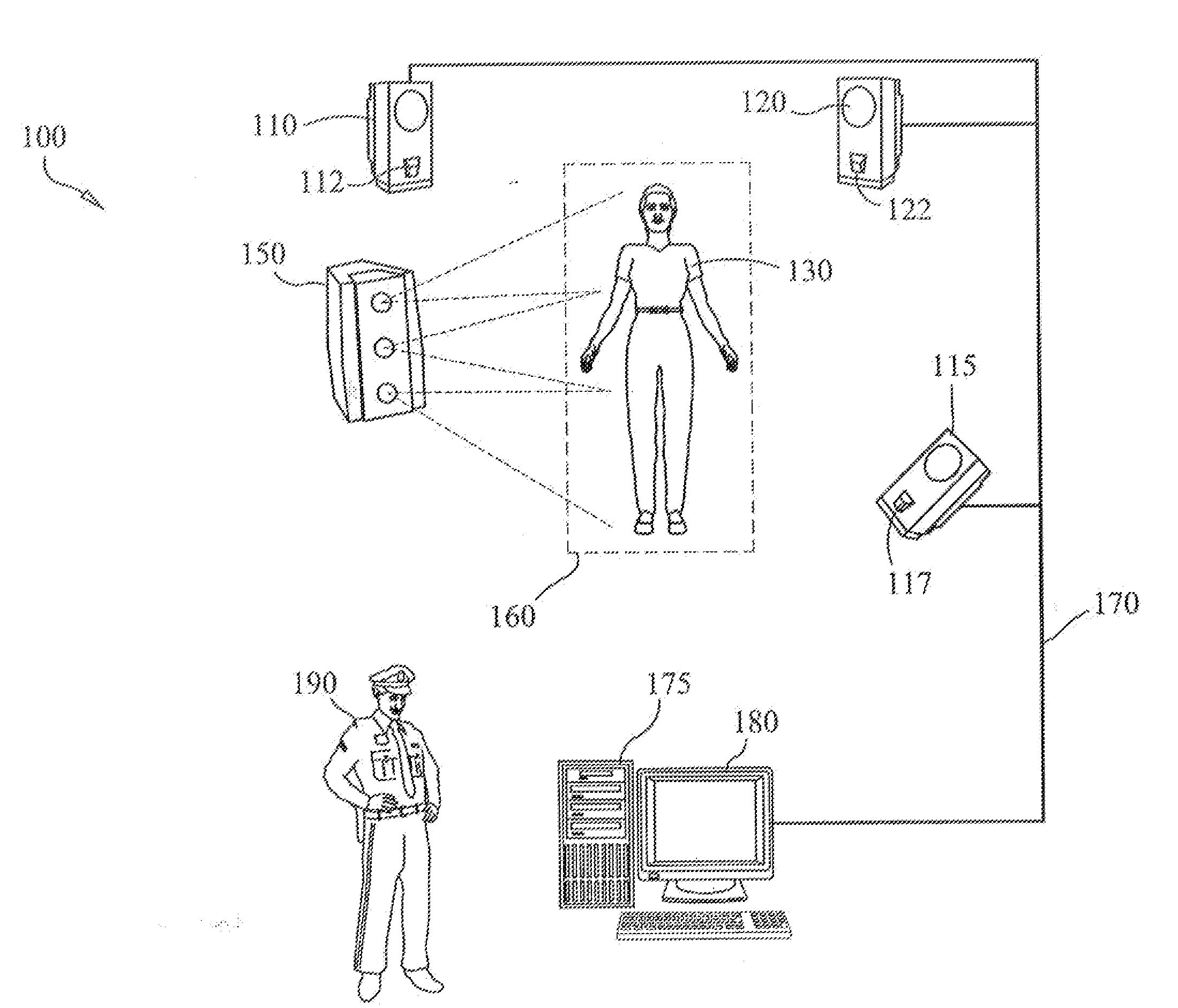
[0013]In accordance with the present invention, a multiple camera imaging method and system successfully addresses the risk to security personnel from dangerous concealed objects on an individual. The imaging system is operative to perform a full, surrounding field of observation of an individual for optical contrast-based information representative of the presence of one or more objects concealed on the person being searched. The ability of the multiple camera imaging system to conduct a complete search of the individual from a full, surrounding imaging perspective makes it unnecessary to place security personnel proximate to the individual during the search. Therefore, the individual can be readily physically isolated if a concealed object is detected. The isolation of the individual can be accomplished by a variety of means including hardened doors at the entrance and exit of the imaging system thereby avoiding potential danger to security personnel and others in the vicinity.
[0018]The security personnel at the workstation may execute a “start” command to control the operation of each camera. A start scan command is effective to cause each camera to begin scanning at an absolute time. The cameras begin operation substantially simultaneously since they are synchronized to the same time base. Each image frame produced by a respective camera includes both a timestamp and a sequence number. This information enables the workstation computer to determine whether the cameras are synchronized to within a prescribed tolerance or to take corrective action.
[0021]Another very important object of the invention is to provide a security system that has the ability to successfully perform without exposing security personnel and innocent by-standers to any potential threat or danger from a concealed object.
[0022]Another important object of the invention is to provide a security system that is non-invasive to the individual being searched for concealed objects.
[0023]Still another very important object of the invention is to provide an improved security system that is easy for security personnel to operate and to synchronize.
[0024]Another object of the invention is to provide an improved security system to identify non-metallic concealed objects on an individual such as explosives.

Problems solved by technology

An inherent deficiency of this type of security system is the fact that it exposes not only the security personnel to danger, but also other individuals (e.g., travelers in an airport) in the vicinity of the security system to the dangers posed by such concealed objects.

Method used


Image

  • Multiple camera imaging method and system for detecting concealed objects
  • Multiple camera imaging method and system for detecting concealed objects
  • Multiple camera imaging method and system for detecting concealed objects

Examples


Embodiment Construction

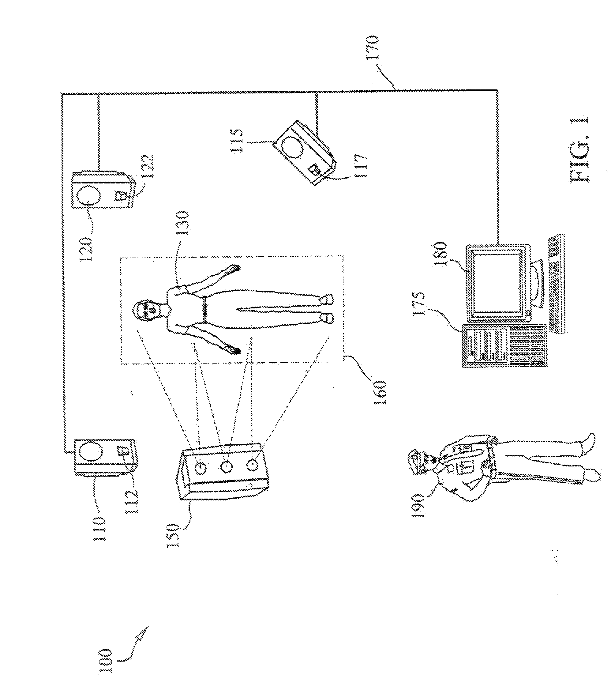
[0032]FIG. 1 diagrammatically illustrates the preferred embodiment of the present invention. As shown therein, the imaging system 100 includes a plurality of millimeter wave cameras 110, 115, 120. The millimeter wave cameras 110, 115, 120 are spatially deployed relative to a prescribed imaging zone 160 through which an individual 130 to be searched must pass, so that the cameras may be considered to be arranged in a completely circumscribed fashion about that imaging zone 160. It should be noted that the invention is not limited to the three millimeter wave cameras of the illustrated example, or any particular number. What is necessary is that the number of millimeter wave cameras deployed about the imaging zone 160 is sufficient to perform a full, surrounding field of observation of a person 130 within the imaging zone 160.

[0033]The millimeter wave cameras 110, 115, 120 are detection devices that are operative to detect differences or contrast between millimeter wave energy (e.g. e...


PUM


Abstract

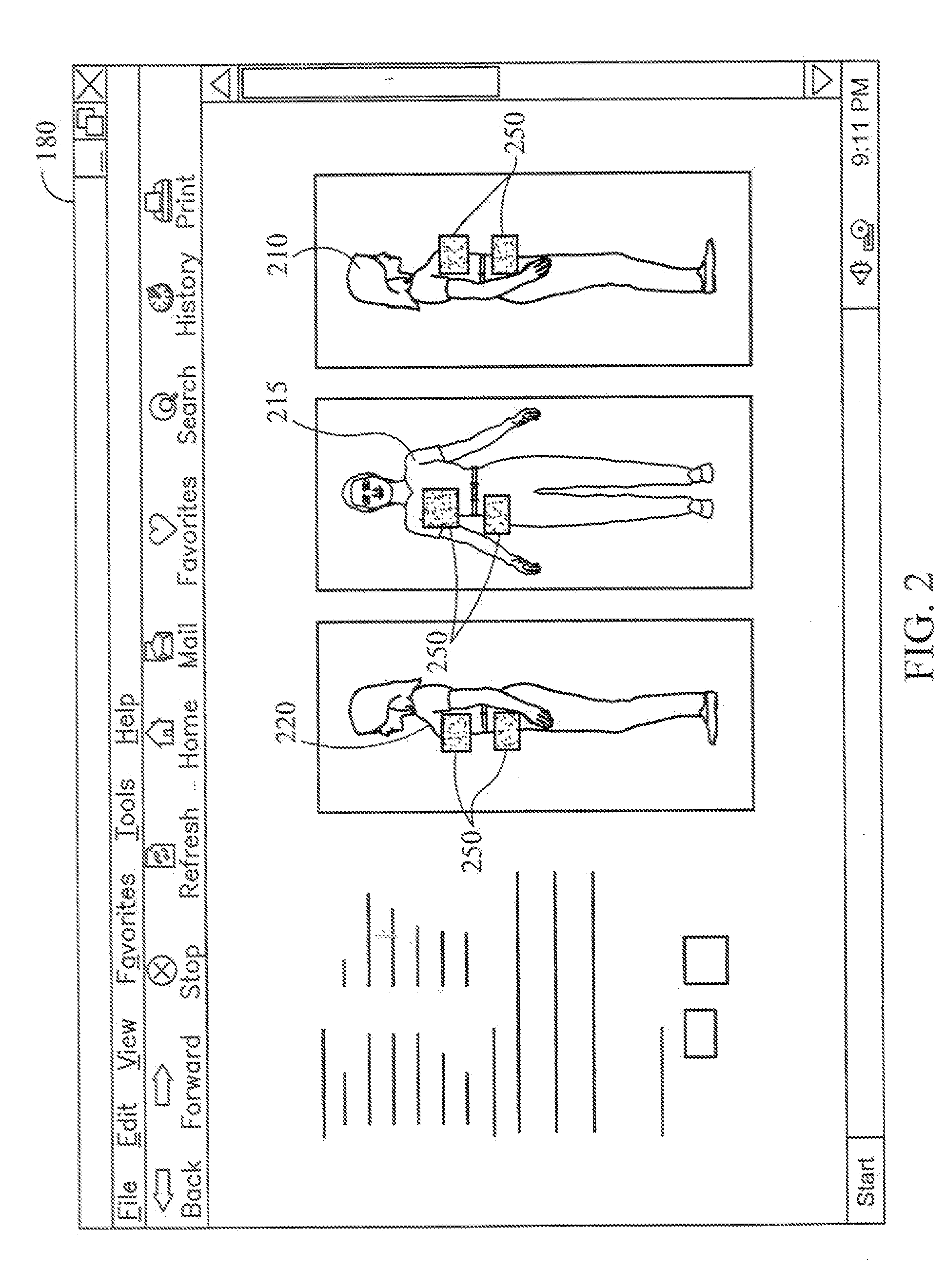
The present invention is an imaging system for detecting concealed objects on an individual. The imaging system includes an imaging zone that is illuminated with millimeter wave energy. A plurality of millimeter wave cameras are focused to fully surround the imaging zone and have the ability to detect millimeter wave frequencies reflected from the imaging zone. As an individual passes through the imaging zone the plurality of millimeter wave cameras detect concealed objects by identifying differences in the millimeter wave energy reflected by the individual's body and a concealed object. A composite image is generated by a central processing unit and displayed on a monitor showing the concealed object on the individual through optical contrast.

Description

BACKGROUND OF THE INVENTION[0001]1. Field of the Invention[0002]The present invention relates generally to security systems, and more specifically to using multiple millimeter wave cameras to detect concealed objects on an individual.[0003]2. Description of the Prior Art[0004]Security systems can be found at transportation centers such as airports, train stations or at other public facilities such as courthouses, government buildings, or public schools. One of the principal concerns of operators of security systems is the need to protect security personnel and other individuals (e.g. the general public) in the course of conducting a search of a person for concealed objects. The concealed objects that present a danger are weapons, explosives, contraband and other similar items.[0005]Prior art security systems include metal or chemical residue detectors that require security personnel to be in proximity of the individual. One or more security personnel are required to conduct a hands-...

Claims


Application Information

Patent Timeline
IPC IPC(8): G06K9/00H04N5/225
CPCH04N5/272G06K2209/09G06V2201/05
Inventor ANDREW, BRIANCARTER, JOHN
Owner MICROSEMI
Learn More