Artificial knee joint

a knee joint and artificial technology, applied in knee joints, prostheses, medical science, etc., can solve the problems of increasing the possibility of fracture after the operation, and the excision of the tibia is more extensiv

Inactive Publication Date: 2009-02-12
KYOCERA CORP +1
View PDF18 Cites 126 Cited by
  • Summary
  • Abstract
  • Description
  • Claims
  • Application Information

AI Technical Summary

Benefits of technology

[0028]The artificial knee joint of the present invention has a movable range of bending angles from 0 to 180 degrees, and enables deep knee bending of up to 180 degrees in theory. This makes it possible, not only to make deep knee bending while avoiding Osseous impingement, but also...

Problems solved by technology

There has been such a problem that increasing the thickness of the insert plate leads to a grea...

Method used


Image

  • Artificial knee joint
  • Artificial knee joint
  • Artificial knee joint

Examples


first embodiment

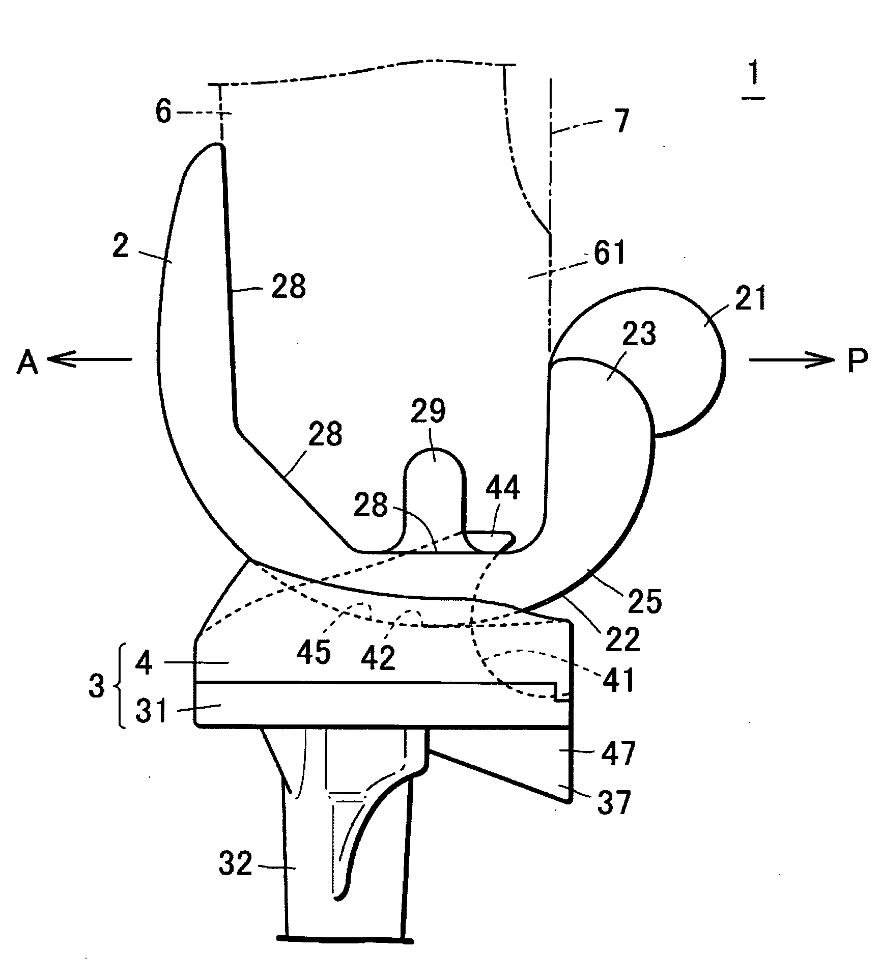
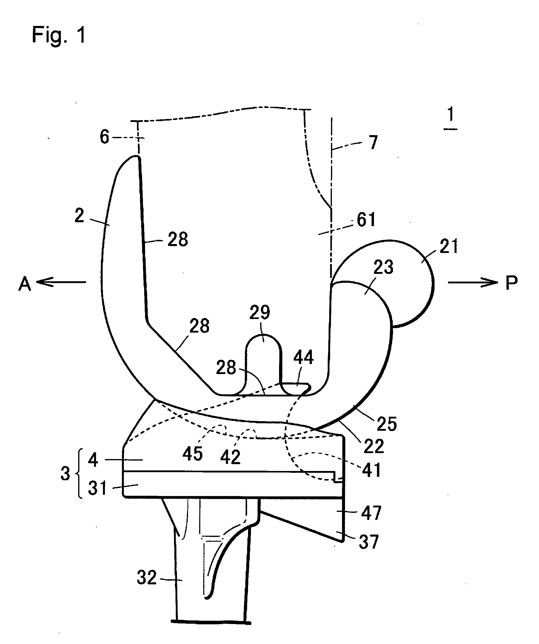
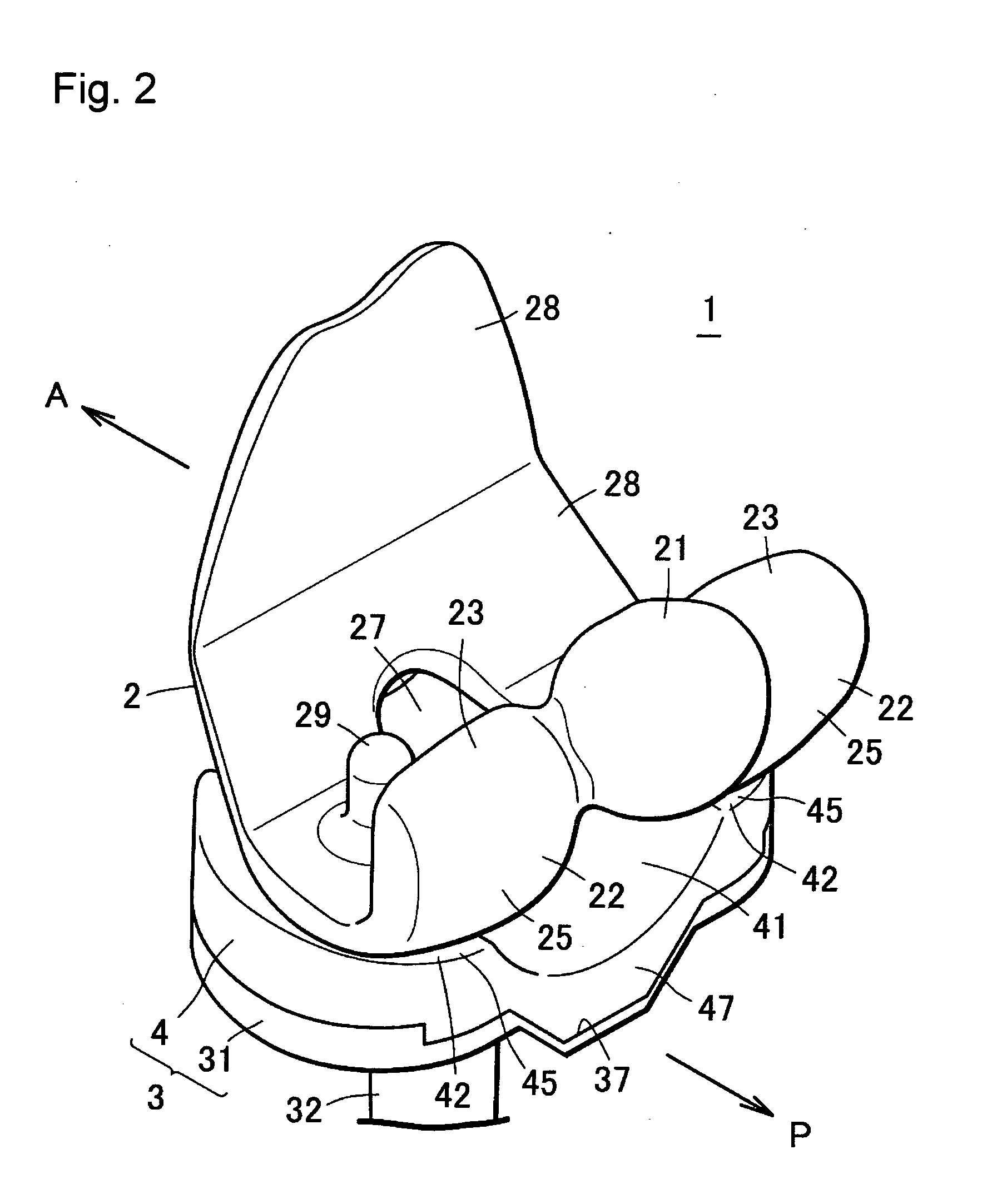
[0071]An artificial knee joint 1 of the present invention comprises a femoral component 2 fixed onto the distal portion of the femur and a tibial component 3 fixed onto the proximal portion of the tibia as shown in FIGS. 1 through 5.

[0072]The femoral component 2 comprises two femoral articular surfaces 25 of bulging and curved shapes, and a cam 21 of spheroidal or substantially cylindrical shape that is provided on the rear end 23 of the femoral articular surface 25 and protrudes from the femoral articular surface 25.

[0073]The tibial component 3 comprises a tibial tray 31 fixed onto the proximal portion of the tibia and an insert plate 4 fixed onto the top surface of the tibial tray 31.

[0074]The insert plate comprises two tibia articular surfaces 45 that make contact respectively with the two femoral articular surfaces 25 and a cam-receiving slide surface 41 that contacts the cam 21 and slides against the femoral component 2 in contact therewith.

[0075]When the knee is extended, the ...

second embodiment

[0098]The artificial knee joint of this embodiment comprises the femoral component 2 and the tibial component 3 similarly to the first embodiment, although the cam 21 is fixed onto the rear end 23 of the femoral component 2 so as to be slidable, and the amount of offset can be adjusted by changing the amount of protrusion of the cam 21 beyond the femoral articular surface 25.

[0099]A cam hole 26 is formed on the rear end 23 of the femoral component 2 as shown in FIG. 10, and the cam 21 is secured by inserting the cam stem 24 into the cam hole 26. The cam stem 24 and the cam hole 26 are secured together by forming an engaging mechanism on the surface of the cam stem 24 and on the medial surface of the cam hole 26, or by employing separate engagement members. Also the position of the cam stem 24 within the cam hole 26 can be changed by releasing the members from engagement, so as to move the cam stem 24, for example, to the position of cam stem 24′. Fixing the cam stem 24′ in the cam h...

third embodiment

[0102]The artificial knee joint of this embodiment comprises the femoral component 2 and the tibial component 3 similarly to the first embodiment, but is characterized in that the insert plate has a protrusion that inclines downward provided on the back surface at the mid position corresponding to the cam-receiving slide surface, and the tibial tray has a recess that accommodates the protrusion that tilts downward.

[0103]The artificial knee joint 1 of the present invention enables the knee to bend by means of the first sliding state and the second sliding state, while repetition of the sliding motion causes the insert plate 4 to wear. Therefore, it is necessary to set the thickness of the insert plate 4 so that the distance between the tibial articular surface 45 and the bottom of the cam-receiving slide surface 41 is not less than a predetermined thickness t that is set by taking the wear loss into account.

[0104]FIG. 12(B) shows the artificial knee joint 1 having the insert plate 4 ...


PUM


Abstract

An artificial knee joint that compresses both osseous impingement and soft tissue impingement from occurring and can endure usage over a long period of time is provided.
The artificial knee joint of the present invention comprises a femoral component, a tibial tray and an insert plate fixed onto the top surface of the tibial tray. The femoral component comprises a femoral articular surface and a cam that is provided on the rear end of the femoral articular surface and protrudes from the femoral articular surface, the insert plate comprises a tibial articular surface that makes contact with the femoral articular surface and a cam-receiving slide surface that makes contact with the cam. When the knee is extended, the joint takes a first sliding state in which the femoral articular surface slides against the tibial articular surface. When the knee is bent at an angle in a range from 90 to 160 degrees, the joint shifts from the first sliding state to a second sliding state in which the cam slides on the cam-receiving slide surface. When the knee is bent deeply with a bending angle of 180 degrees, the second sliding state is assumed in which a resection surface of the femoral component and the rear end of the insert plate are offset.

Description

BACKGROUND OF THE INVENTION[0001]1. Field of the Invention[0002]The present invention relates to an artificial knee joint used to restore the normal function of a knee joint that has been heavily deformed due to such disease as gonarthrosis or chronic articular rheumatism.[0003]2. Description of the Related Art[0004]An artificial knee joint comprises a femoral component fixed onto the distal portion of the femur, and a tibial component fixed onto the proximal portion of the tibia. As an example of artificial knee joint, such a constitution has been known as a convex sliding surface having a shape of sphere or spheroid formed on a sliding portion located at the middle on the rear end of the femoral component, and a concave surface having a shape of sphere or spheroid formed on a sliding portion located at the middle on the rear end of the tibial component (for example, Japanese Unexamined Patent Publication (Kokai) No. 4-158860). The convex sliding surface and the concave sliding sur...

Claims


Application Information

Patent Timeline
IPC IPC(8): A61F2/38
CPCA61F2/3886A61F2002/30616A61F2002/30604
Inventor HOTOKEBUCHI, TAKAOTAKANO, YASUJU
Owner KYOCERA CORP
Why Eureka
Try Eureka