Safe runway aircraft arrival and departure system using split runway design

Inactive Publication Date: 2009-02-12
GELLERT DANIEL G
View PDF7 Cites 32 Cited by
  • Summary
  • Abstract
  • Description
  • Claims
  • Application Information

AI Technical Summary

Benefits of technology

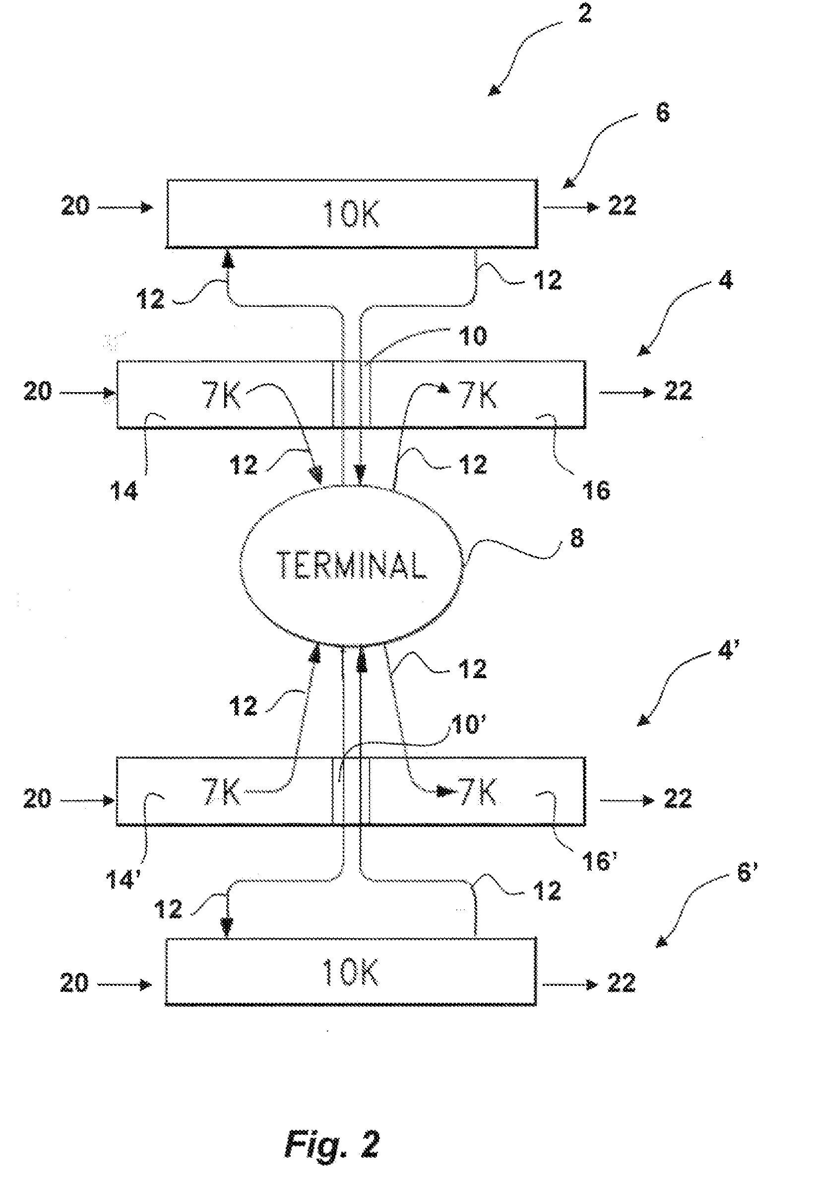
[0015]The inventive Safe Runway Aircraft Arrival and Departure System Using Split Runway Design of this application utilizes existing runways that have been converted into separate portions comprising a landing strip and a takeoff strip. An arriving aircraft lands on the designated landing strip portion of the runway, and a departing aircraft takes off from the designated takeoff strip p

Problems solved by technology

Airports world wide are experiencing increased gridlock and associated delays in aircraft arrivals and departures.
Airports track the number and time between aircraft arrivals and departures on the runways as “arrival and departure sequences.” It is anticipated that air traffic will increase enormously during the coming decades, and with it, will come increased delays between the times aircraft can arrive and depart on the runways, causing delayed arrival and departure sequences.
Increased air traffic causes aircraft in the air to be forced into holding patterns, while aircraft on the ground are forced to sit idle on the tarmac or slowly move in a takeoff queue.
The delayed arrival and departure sequences directly lead to fuel cost increases, flight time increases, passenger ticket increases, and passenger dissatisfaction.
The detrimental financial impact of the delays is already being felt by the airlines.
Moreover, the construction at many airports will not be possible given rising land costs and growing development around existing airports.
The land required for new runways is not available for many, if not most, airports.
Increased Risk of Accidents Caused by Runway Incursions and Air Vortices
Given the current and anticipated increase in air traffic world wide, there is a corresponding increase in the risk of airplane accidents caused by runway incursions and air vortices or wake turbulence.
When an aircraft enters an active runway due to human and/or equipment error, the aircraft is at

Method used


Image

  • Safe runway aircraft arrival and departure system using split runway design
  • Safe runway aircraft arrival and departure system using split runway design
  • Safe runway aircraft arrival and departure system using split runway design

Examples


Embodiment Construction

:

[0020]The following detailed description illustrates the invention by way of example, not by way of limitation of the scope, equivalents or principles of the invention. This description will enable one skilled in the art to make and use the invention, and describes several embodiments, adaptations, variations, alternatives and uses of the invention.

[0021]Safe Runway Aircraft Arrival and Departure System Using Split Runway Design

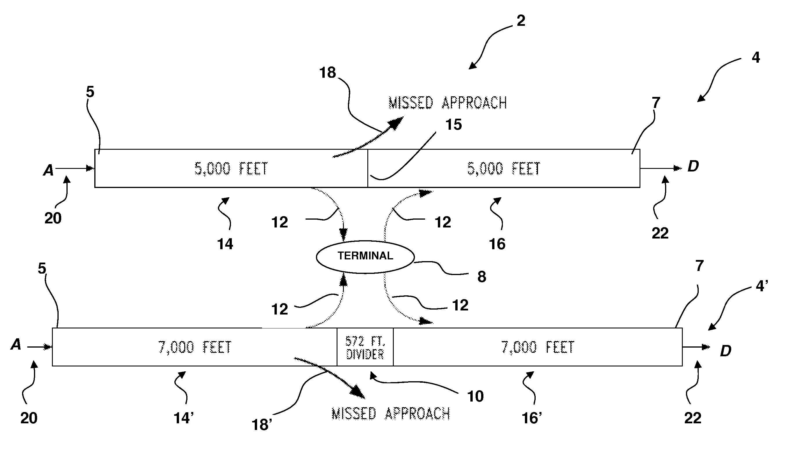
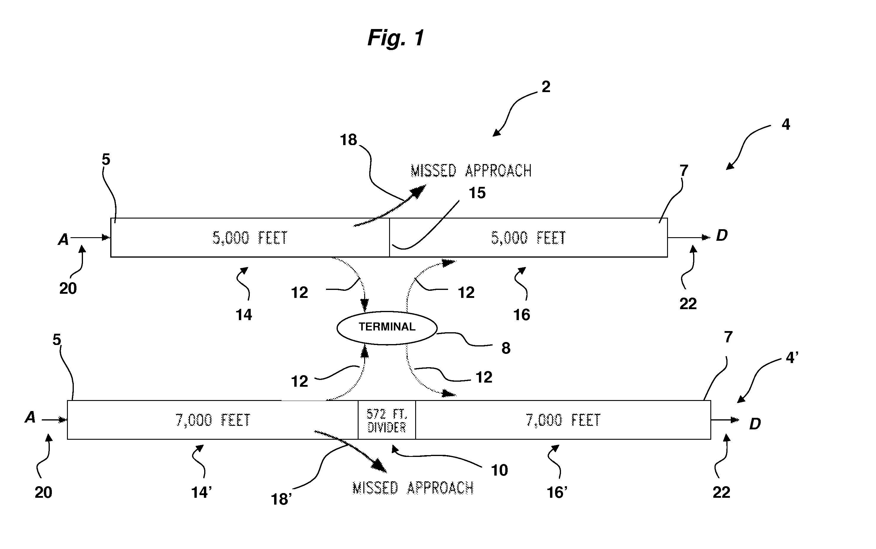
[0022]FIG. 1 shows an exemplary Safe Runway Aircraft Arrival and Departure System Using Split Runway Design 2 with airport terminal 8, two split runways 4, 4′, a buffer zone 10, and designated missed approach flight paths 18, 18′. The shorter split runway 4 is an existing linear runway 10,000 feet long divided medially between opposed first and second ends 5, 7 into two equal portions, a landing strip 14 5,000 feet long and a takeoff strip 16 5,000 feet long. A dividing line 15 separates the landing 14 and takeoff strips 16. The line 15 is a painted strip cr...


PUM


Abstract

A Safe Runway Aircraft Arrival and Departure System Using Split Runway Design comprising a linear runway divided into separate landing strip and takeoff strip portions. Arriving aircraft land on the designated landing strip portion of the runway, while departing aircraft take off from the designated takeoff strip portion of the runway. The landing and takeoff portions may be separated by a defined buffer zone utilized by aircraft for taxiing to and from a terminal. Existing runways may be readily converted into two designated portions for arriving and departing aircraft, thereby significantly increasing the number of aircraft arrival and departure sequences, reducing the likelihood of aircraft runway incursions, eliminating dangerous intersection takeoffs, and conserving jet fuel.

Description

CROSS REFERENCE TO RELATED APPLICATION[0001]This application claims priority under 35 USC 119(e) of Provisional Patent Application Ser. No. 60 / 954,276 filed Aug. 6, 2007, entitled “System For Increasing Airport Aircraft L / TO Capacity by Utilizing Vertically Separated Approaches (VSA) and Takeoffs (VST) and Provisional Patent Application Ser. No. 60 / 976,646 filed Oct. 1, 2007, entitled “Advanced Air Traffic Management System Using Split Run-Way Scheduling and VSA / VST Operations” hereby incorporated by reference in their entirety.FIELD OF THE INVENTION[0002]The present invention relates generally to improved airport operation, and more particularly to an airport runway system and method of design for converting existing runways into two sections for arriving and departing aircraft, thereby significantly increasing the number of aircraft arrival and departure sequences, reducing the likelihood of aircraft runway incursions, and also conserving jet fuel.BACKGROUND OF THE INVENTION[0003]...

Claims


Application Information

Patent Timeline
IPC IPC(8): G08G5/06B64D15/00
CPCY02T50/82B64F1/00Y02T50/80
Inventor GELLERT, DANIEL G.
Owner GELLERT DANIEL G
Why Eureka
Try Eureka