
Handshake Free Sharing in a Computer Architecture

a computer architecture and handshake technology, applied in computing, instruments, data conversion, etc., can solve the problems of unsuitable methods, lack of error detection and correction provisions, and complexity of handshake protocols

Active Publication Date: 2009-02-12
WINBOND ELECTRONICS CORP
View PDF15 Cites 11 Cited by
  • Summary
  • Abstract
  • Description
  • Claims
  • Application Information

AI Technical Summary

Benefits of technology

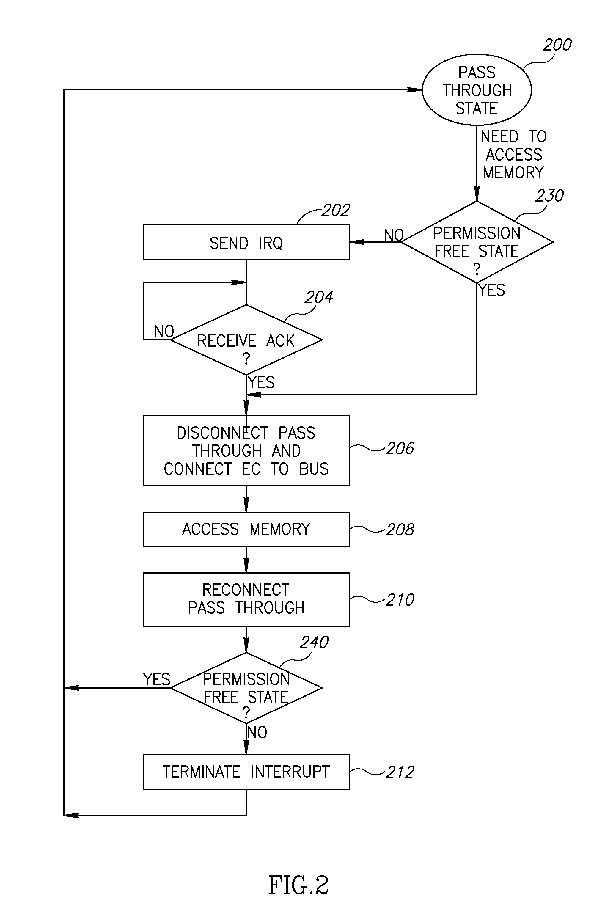
[0021]There is further provided in accordance with an exemplary embodiment of the invention, a processor comprising a memory interface operative to control a memory unit via a handshake-free protocol, an interrupt interface for transfer of interrupt requests to processors; and a processing unit operative to perform processing tasks and to read data from a memory unit or to store data to the memory unit through the memory interface, the processing unit being configured to transfer an interrupt request through the interrupt interface and receive an acknowledgement of the interrupt request before accessing a memory through the memory interface.
[0022]Optionally, the processing unit is operative to receive the acknowledgement of the interrupt request via the interrupt interface or via a register independent of the interrupt interface. Optionally, the processing unit is operative to read code segments from the memory unit. Optionally, the processor includes an internal memory configured to store less than an entire code of an application to be performed by the processing unit, wherein the internal memory is configured to swap code segments from the memory unit through the memory interface. Optionally, the processing unit is operative to operate in a first state in which it does not transfer an interr

Problems solved by technology

The main disadvantage of handshake protocols is their complexity, as in some applications, a simpler protocol is sufficient.
It also lacks error detection and correction provisions.
This requires that the processors support the handshake protocol, and is complex when more than two processors are involved.
This method is unsuitable for applications wherein intermittent access to the memory is required by both processors.
While this may solve the problem of accessing the BIOS, it does not allow intermittent access to the memory unit.
Furthermore, this solution requires a memory with a parallel access interface and is not suitable for a serial interface.

Method used


Image

  • Handshake Free Sharing in a Computer Architecture
  • Handshake Free Sharing in a Computer Architecture
  • Handshake Free Sharing in a Computer Architecture

Examples


Embodiment Construction

Overview

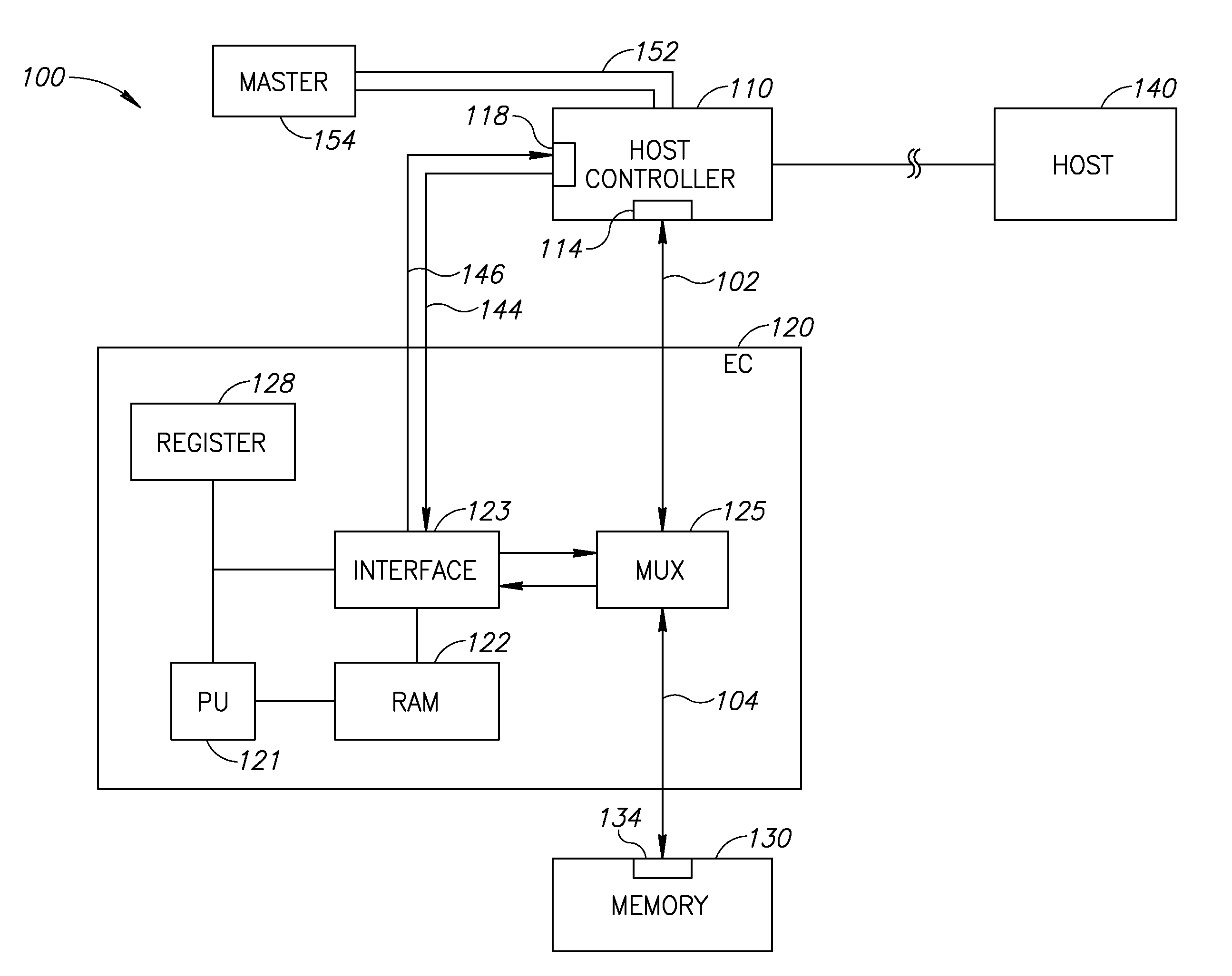
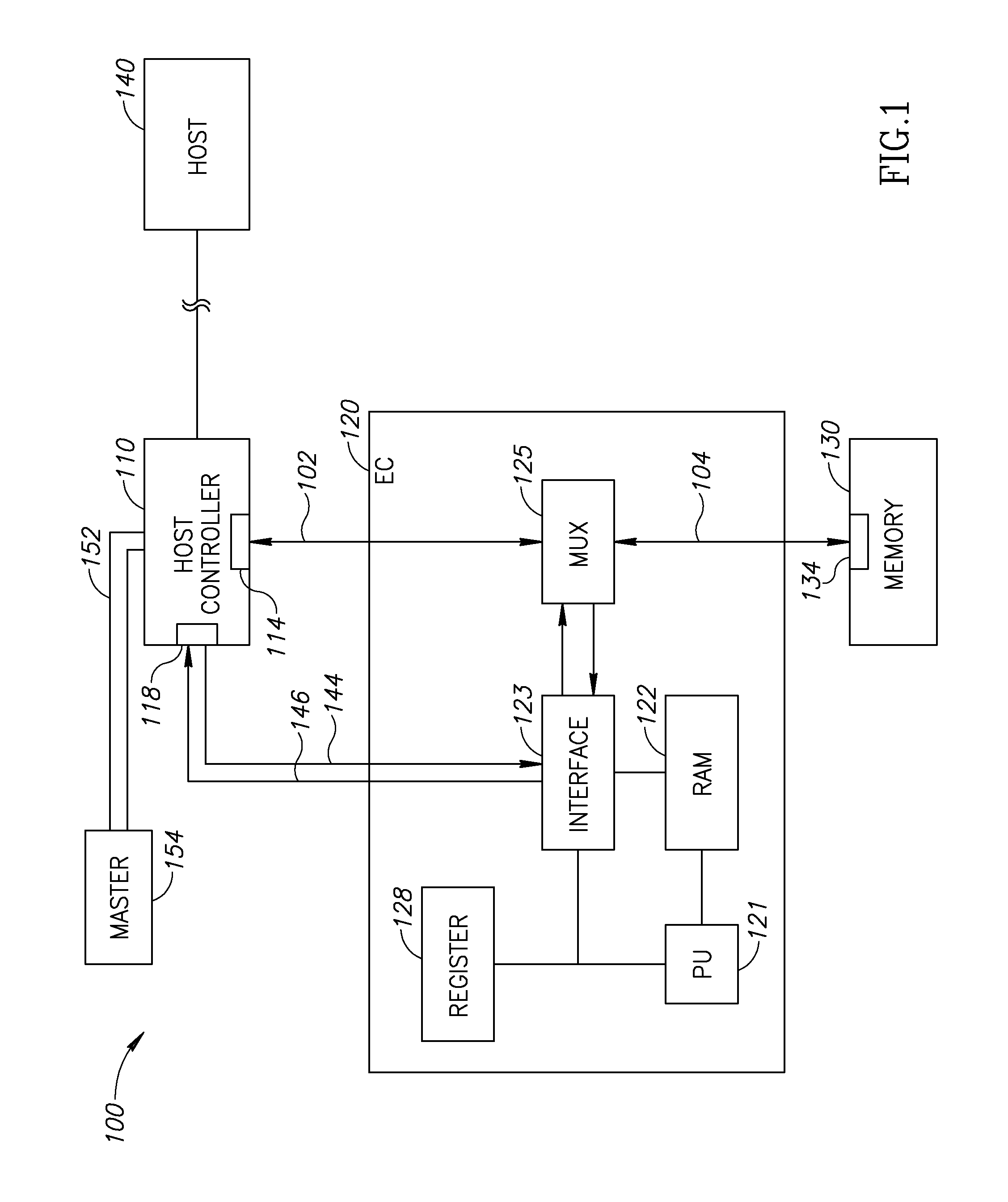
[0029]FIG. 1 is a schematic illustration of memory connections of a memory unit 130 servicing a plurality of processors of a computer 100 wherein for simplicity, only portions relevant to explaining an exemplary embodiment of the present invention are shown. Memory unit 130 is designed with an SPI interface 134, such that memory accesses to memory unit 130 are in accordance with the SPI protocol. Memory unit 130 may include substantially any suitable type of memory, such as a flash memory, a ROM and / or other non-volatile memory. Memory unit 130 may be of substantially any capacity, for example at least 1 Mbyte, 4 Mbyte or even at least 16 Mbyte. Memory unit 130 may be a read only memory or a read / write memory.

[0030]A host controller 110 (also known as a Southbridge and / or an I / O controller hub) is connected, via an SPI interface 114 thereof, to memory unit 130 through an SPI bus formed of a first segment 102 and a second segment 104. In some embodiments of the invention, hos...


PUM


Abstract

A system arrangement including a memory unit having a memory interface in accordance with a handshake-free protocol between the memory and an accessing master, a bus connected to the memory unit and first and second masters. The first master operative to access the memory unit through the bus and the memory interface and operative to perform interrupts following reception of an interrupt request through an interrupt interface. The second master operative to access the memory unit through the bus and memory interface. The second master being configured to transfer an interrupt request to the first processor before accessing the memory unit.

Description

FIELD OF THE INVENTION[0001]The present invention relates generally to computer architectures and specifically, but not exclusively, to memory access architectures.BACKGROUND[0002]Processors are used for a very wide range of tasks, including, inter alia, mathematical calculations, database management, communications and the controlling of devices. In many cases, processors require a separate memory unit, for performing functions such as the storage of processing results or intermediate values, and / or from which to retrieve operation software and / or input data. A processor which controls the access to the memory is referred to as a “master”. The term master is also used to represent other units, not necessarily processors, which control access to a memory.[0003]A variety of communication protocols have been defined for internal communication purposes, including data transfer between the processor and the memory unit. Some protocols were defined particularly for use in multi-processor...

Claims


Application Information

Patent Timeline
IPC IPC(8): G06F3/00
CPCG06F13/24G06F13/1663
Inventor SCHRAMM, MICHALTASHER, NIR
Owner WINBOND ELECTRONICS CORP
Learn More