
Machine for pipe maintenance

Inactive Publication Date: 2009-02-19
KMC ROBOTICS CO LTD
View PDF6 Cites 51 Cited by
  • Summary
  • Abstract
  • Description
  • Claims
  • Application Information

AI Technical Summary

Benefits of technology

[0016]An object of the invention is to provide a machine for pipe maintenance that makes it possible to repair and maintain water supply and drain pipes without needing to replace a pipe by effectively removing foreign substances sticking to the inside of the water supply and drain pipes.
[0018]According to the machine of the invention, it is possible to effectively remove foreign substances sticking to the inside of a pipeline, using friction members that are moved along the inside of the pipeline by a rotator assembly and rotated by rotating shaft assemblies that which come in contact with the inside of the pipeline.
[0019]Further, rotating shaft assemblies and a rotator assembly are respectively rotated by first and second rotating units, such that it is possible to maximize the effect of removing the foreign substances in the pipeline by smoothly rotating the friction members, and also to improve durability by preventing erroneous operations and damage due to load that is applied during the operation.
[0020]Therefore, by periodically removing the foreign substances inside the pipeline during the maintenance of water supply and drain pipes, it is possible to reduce the time and cost needed to maintain the water supply and drain pipes and supply pure and sanitary water to each house or building.

Problems solved by technology

The water supply pipe is a pipe for supplying water into a building as described above, but has a problem in that rust or other foreign substances stick to the inside of the pipelines after the pipes have been under the ground over a long period of time, causing contaminated water to be supplied into the building.
Further, the drain pipe is a pipe for draining sewage used in the building and transporting water to sewage facilities, which also has a problem in that dregs contained in the sewage stick to the inside of the pipelines, such that it is difficult to drain sewage, if in excess, the pipelines are blocked and the sewage cannot be drained and flows backward into the building.
According to this method of maintaining the water supply and drain pipes, since it is required to dig the ground and then replace the pipe, not only does this cause high cost to replace the pipe but also obstructs the traffic due to a long construction period.
Further, because water supply should be stopped, this inconveniences the residents of the building.
As a result, the rotating link and the polishing roller cannot smoothly rotate and the efficiency of polishing was reduced, such that it was difficult to cleanly remove the foreign substances in the pipeline.
Further, the self-propelled car uses the polishing roller, of which the outside comes in contact with the inside of the pipeline, to grind and remove the foreign substances, but the contact area between the outside of the polishing roller and the inside of the pipeline is small, such that it was difficult to effectively remove the foreign substances in the pipeline.
Further, according to the self-propelled car for polishing a pipe, since the rotational directions of the rotating link and the polishing roller are the same, the polishing roller frequently slips while removing the foreign substances, such that it was difficult to effectively remove the foreign substances in the pipeline.

Method used


Image

  • Machine for pipe maintenance
  • Machine for pipe maintenance
  • Machine for pipe maintenance

Examples


Embodiment Construction

[0031]Hereinafter, preferred embodiments of the invention are described in detail with reference to the accompanying drawings.

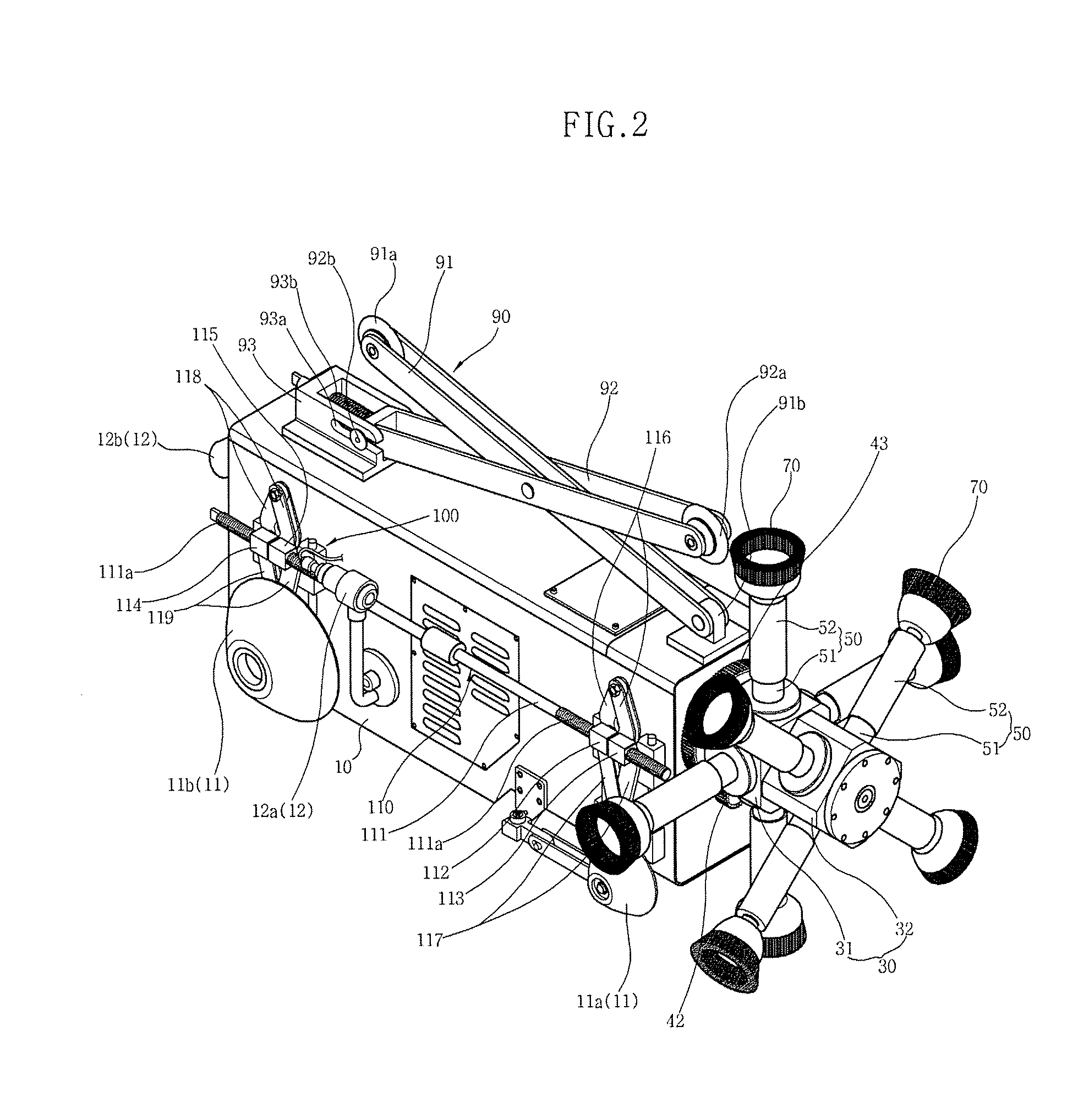
[0032]FIG. 2 is a perspective view of an embodiment of the invention, showing the entire shape of a machine for pipe maintenance of the invention.

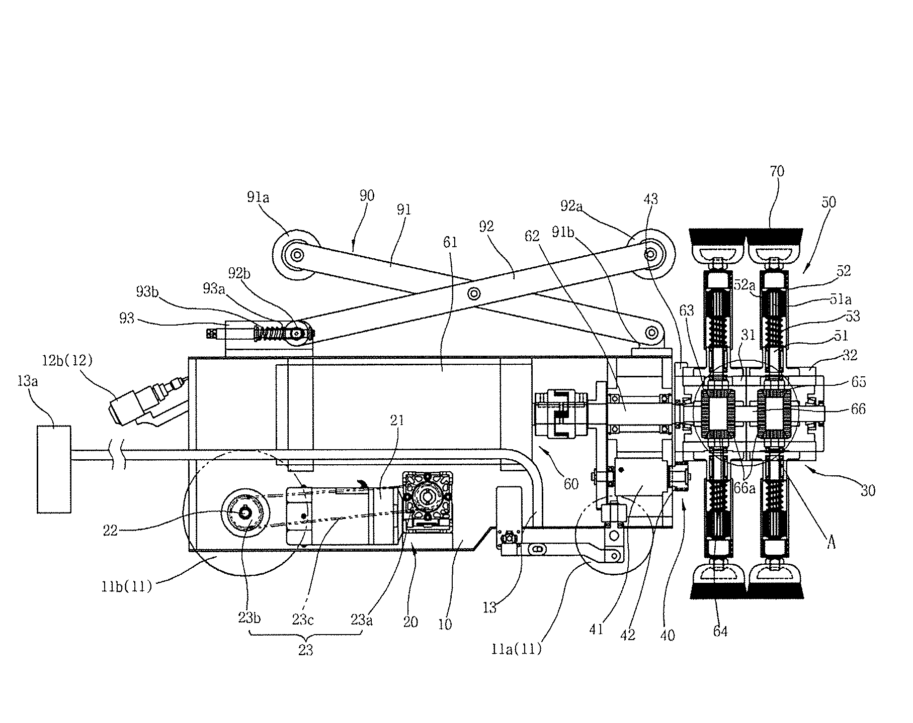
[0033]FIG. 3 is a cross-sectional view showing the internal structure of an embodiment of the invention, illustrating the configuration of a base housing equipped with a traveling unit and first and second rotating units and the configuration of a rotator assembly including a power transmission gear assembly and rotating shaft assemblies.

[0034]FIG. 4 is an enlarged view of the portion indicated by ‘A’ of FIG. 3, showing the enlarged power transmission structure of the second rotating unit.

[0035]FIGS. 5A to 5C are views illustrating an exemplary use of another embodiment of the invention, illustrating the configuration and operation of an emergency control member that removes the load applied to the driving shaft whe...


PUM


Abstract

A machine for pipe maintenance, which travels forward through a pipeline and effectively removes foreign substances sticking to the inside of a pipeline, using friction members 70 that are moved along the inside of the pipeline by a rotator assembly 30 and rotated by rotating shaft assemblies 50, which come in contact with the inside of the pipeline is disclosed. Further, rotating shaft assemblies 50 and a rotator assembly 30 are respectively rotated by first and second rotating units 40, 60, such that it is possible to maximize the effect of removing foreign substances in the pipeline by smoothly rotating the friction members 70, and also improve durability by preventing an erroneous operation and damage due to load that is applied during the operation.

Description

BACKGROUND OF THE INVENTION[0001]1. Field of the Invention[0002]The present invention relates to a machine for pipe maintenance, particularly a machine that facilitates repair and maintenance of water supply and drain pipes placed under the ground by removing foreign substances sticking to the inside of the pipelines.[0003]2. Description of the Related Art[0004]In general, water supply and drain pipes, used to supply water to buildings, such as a house, a commercial building, and a factory, and drain used water from the buildings, are generally under the ground and connected to water supply facilities for supplying water or sewage facilities for treating drained water.[0005]The water supply pipe is a pipe for supplying water into a building as described above, but has a problem in that rust or other foreign substances stick to the inside of the pipelines after the pipes have been under the ground over a long period of time, causing contaminated water to be supplied into the building...

Claims


Application Information

Patent Timeline
IPC IPC(8): B08B9/04
CPCB08B9/049B08B9/051B08B9/0492B08B5/04B08B9/032B08B9/0436B08B9/045H04N7/18H04Q9/00
Inventor SEO, SANGYOUNG
Owner KMC ROBOTICS CO LTD
Features
  • Generate Ideas
  • Intellectual Property
  • Life Sciences
  • Materials
  • Tech Scout
  • Unparalleled Data Quality
  • Higher Quality Content
  • 60% Fewer Hallucinations
Learn More