
Particulate Filter Regeneration

a technology of particulate filter and filter body, which is applied in the direction of machine/engine, mechanical equipment, separation processes, etc., can solve the problems of reducing engine performance, increasing exhaust pressure, and reducing performance impact, so as to reduce engine performance, increase exhaust pressure, and reduce performance impact

Active Publication Date: 2009-02-19
FORD GLOBAL TECH LLC
View PDF17 Cites 21 Cited by
  • Summary
  • Abstract
  • Description
  • Claims
  • Application Information

AI Technical Summary

Benefits of technology

[0001]Diesel powertrains may have a particulate filtration system referred to as a Diesel Particulate Filter (DPF), where engine generated soot may be collected. The collection, or loading, of soot leads to an increase in exhaust pressure, which may degrade engine performance. As such, collected soot can be periodically combusted (e.g., regenerated, or purged) to clean the device and reduce the performance impact.
[0002]It may be advantageous to vary when a particulate filter is regenerated to reduce fuel consumption and extend filter usable life. In some examples, filter soot loading may be inferred and / or correlated to a measure of filter flow restriction, such as based on upstream and / or downstream pressures. However, the restriction over the DPF may depend heavily on the amount of flow, which in turn may vary with temperature in and around the DPF. Further, since temperature may vary both along the length of the filter and / or across the filter width, especially during transients, using a measure or estimate of DPF temperature and / or exhaust temperature may produce errors, especially during low flow conditions (e.g., idle) where errors in models may be amplified. Such errors may lead to unnecessary regeneration, thus increasing fuel usage and decreasing durability.
[0003]Thus, in one approach, the restriction and / or the decision and timing of the regeneration may be correlated to loading taking into account temperature and / or flow distribution along and / or across the DPF. Further, in one embodiment, such correlation may be used during higher flow and / or higher temperature conditions to provide improved accuracy and address the problem of low flow restriction variability.

Problems solved by technology

The collection, or loading, of soot leads to an increase in exhaust pressure, which may degrade engine performance.
As such, collected soot can be periodically combusted (e.g., regenerated, or purged) to clean the device and reduce the performance impact.
However, the restriction over the DPF may depend heavily on the amount of flow, which in turn may vary with temperature in and around the DPF.
Further, since temperature may vary both along the length of the filter and / or across the filter width, especially during transients, using a measure or estimate of DPF temperature and / or exhaust temperature may produce errors, especially during low flow conditions (e.g., idle) where errors in models may be amplified.
Such errors may lead to unnecessary regeneration, thus increasing fuel usage and decreasing durability.

Method used


Image

  • Particulate Filter Regeneration
  • Particulate Filter Regeneration
  • Particulate Filter Regeneration

Examples


Embodiment Construction

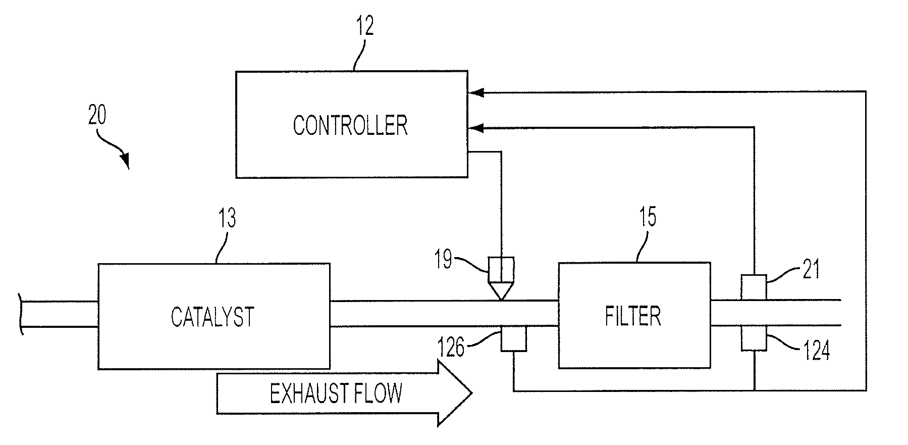
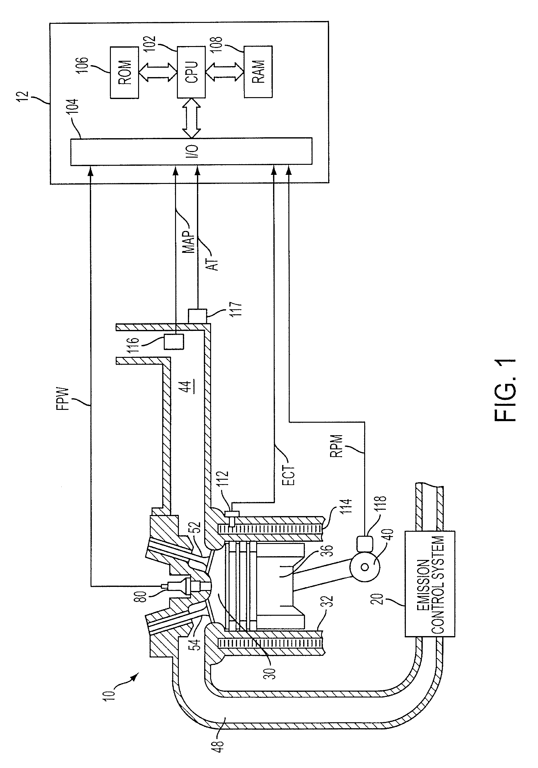
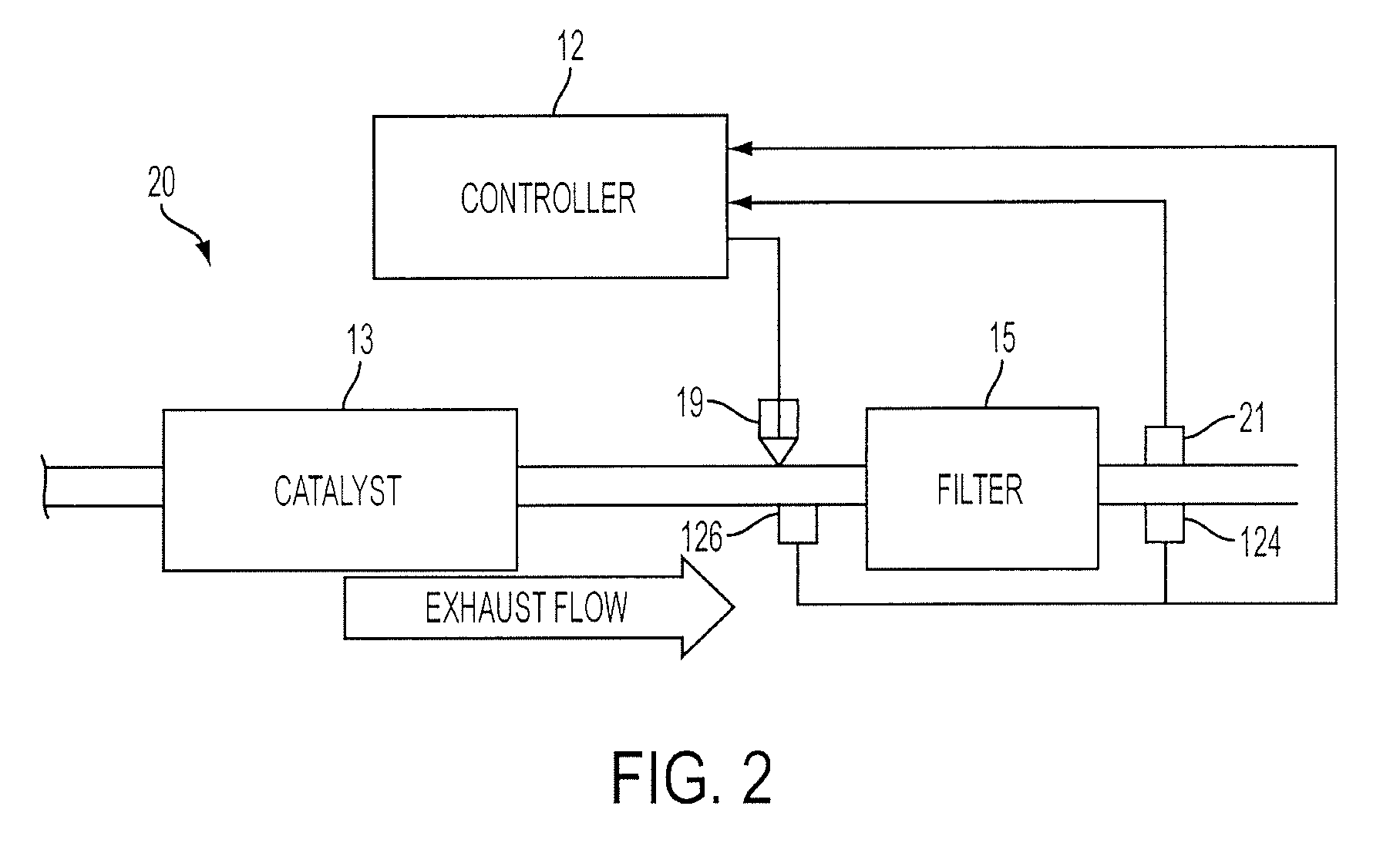
[0010]Internal combustion engine 10, comprising a plurality of cylinders, one cylinder of which is shown in FIG. 1, is controlled by electronic engine controller 12. Engine 10 includes combustion chamber 30 and cylinder walls 32 with piston 36 positioned therein and connected to crankshaft 40. Combustion chamber 30 is shown communicating with intake manifold 44 and exhaust manifold 48 via respective intake valve 52 and exhaust valve 54. Engine 10 is shown as a direct injection engine with injector 80 located to inject fuel directly into cylinder 30. Fuel is delivered to fuel injector 80 by a fuel system (not shown), including a fuel tank, fuel pump, and high pressure common rail system. Fuel injector 80 delivers fuel in proportion to the pulse width of signal FPW from controller 12. Both fuel quantity, controlled by signal FPW and injection timing may be adjustable. Engine 10 may utilize compression ignition combustion under some conditions, for example.

[0011]Controller 12 is shown ...


PUM

PropertyMeasurementUnit
temperatureaaaaaaaaaa
lengthaaaaaaaaaa
depthaaaaaaaaaa

Abstract

In one example, a method of operating an engine having a diesel particulate filter in a vehicle, the particulate filter having a length and depth, includes performing particulate filter regeneration in response to temperature variation across the length and / or depth of the particulate filter.

Description

BACKGROUND AND SUMMARY[0001]Diesel powertrains may have a particulate filtration system referred to as a Diesel Particulate Filter (DPF), where engine generated soot may be collected. The collection, or loading, of soot leads to an increase in exhaust pressure, which may degrade engine performance. As such, collected soot can be periodically combusted (e.g., regenerated, or purged) to clean the device and reduce the performance impact.[0002]It may be advantageous to vary when a particulate filter is regenerated to reduce fuel consumption and extend filter usable life. In some examples, filter soot loading may be inferred and / or correlated to a measure of filter flow restriction, such as based on upstream and / or downstream pressures. However, the restriction over the DPF may depend heavily on the amount of flow, which in turn may vary with temperature in and around the DPF. Further, since temperature may vary both along the length of the filter and / or across the filter width, especia...

Claims


Application Information

Patent Timeline
Patent Type & Authority Applications(United States)
IPC IPC(8): F01N3/00F01N11/00
CPCF01N3/0253F01N9/002Y02T10/47F01N2560/06F01N2900/0408F01N9/005Y02T10/40B01D46/04F01N3/023
Inventor BRAHMA, AVRANIEUWSTADT, MICHIEL VAN
Owner FORD GLOBAL TECH LLC
Learn More