Fuel cell stack flow diversion

a fuel cell and stack technology, applied in capacitors, electrochemical generators, electric propulsion mounting, etc., can solve problems such as poor operation, system damage, and non-positive displacement compressors operating in undesirable conditions, and achieve the effect of reducing or eliminating the expending electrical energy of the fuel cell stack and increasing the flow

Active Publication Date: 2009-02-19
FORD GLOBAL TECH LLC
View PDF5 Cites 9 Cited by
  • Summary
  • Abstract
  • Description
  • Claims
  • Application Information

AI Technical Summary

Benefits of technology

[0014]The control valve may be used to avoid a surge condition in the compressor. The compressor may generate an increased flow to avoid surge. The control valve may then divert the increased flow away from the fuel cell stack.
[0015]According to an embodiment of the present inv

Problems solved by technology

However, non-positive displacement compressors may operate in an undesirable condition known as surge.
Under these c

Method used


Image

  • Fuel cell stack flow diversion
  • Fuel cell stack flow diversion
  • Fuel cell stack flow diversion

Examples


Embodiment Construction

)

[0023]As required, detailed embodiments of the present invention are disclosed herein; however, it is to be understood that the disclosed embodiments are merely exemplary of the invention that may be embodied in various and alternative forms. The figures are not necessarily to scale; some features may be exaggerated or minimized to show details of particular components. Therefore, specific structural and functional details disclosed herein are not to be interpreted as limiting, but merely as a representative basis for the claims and / or as a representative basis for teaching one skilled in the art to utilize the present invention.

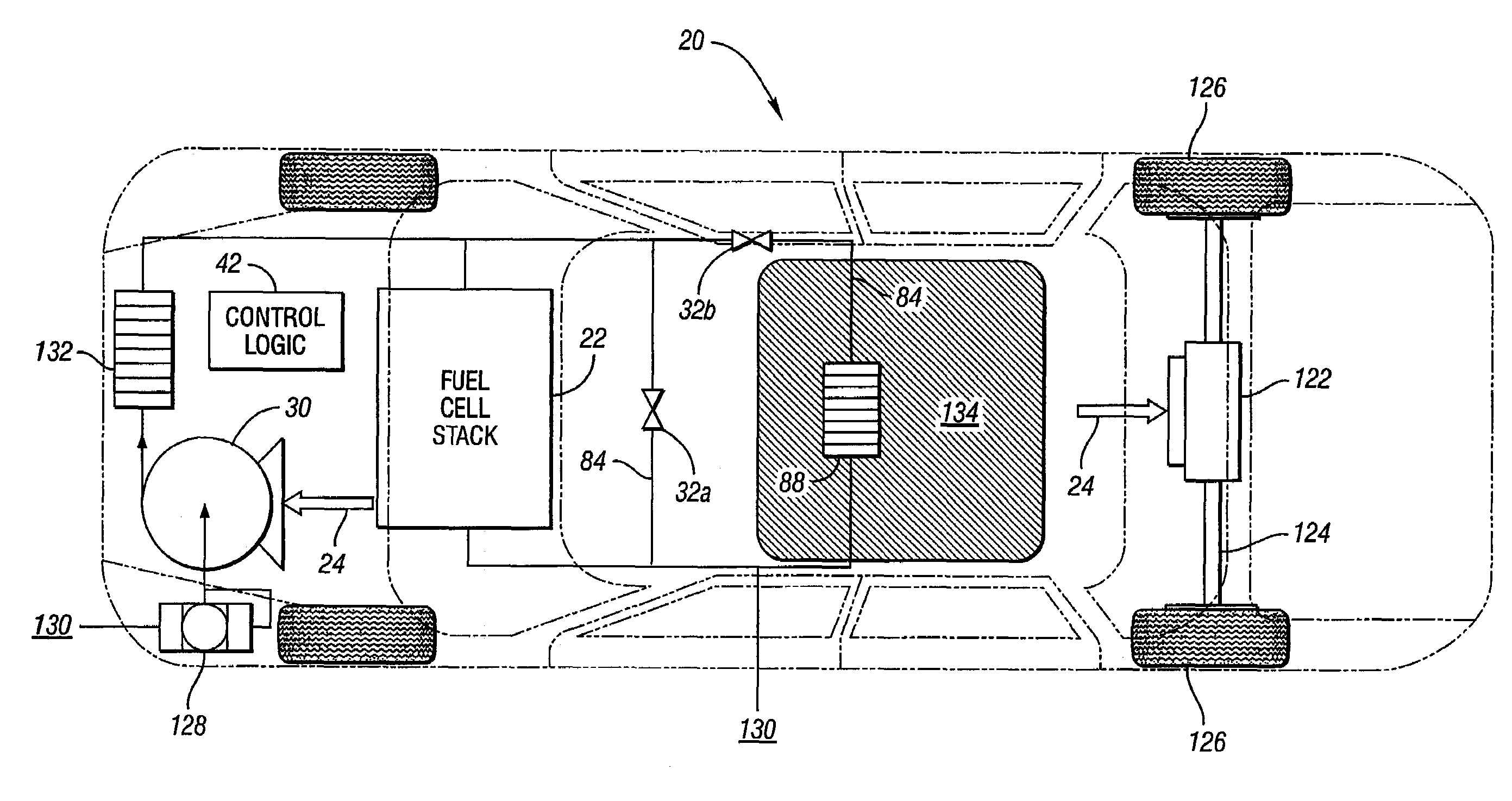
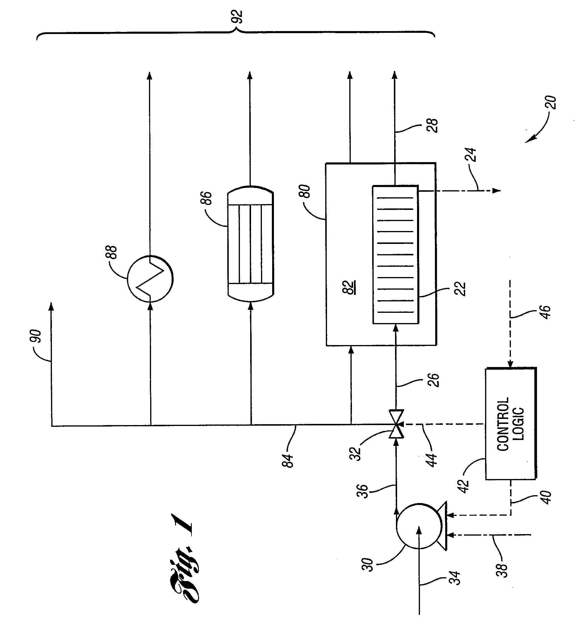
[0024]Referring now to FIG. 1, a schematic diagram illustrating a fuel cell system according to an embodiment of the present invention is shown. A simplified oxidant path of a fuel cell system, shown generally by 20, includes fuel cell stack 22. Fuel cell stack 22 generates electrical energy, shown as 24, by combining ionized fuel and oxidant. The oxidant i...


PUM


Abstract

A fuel cell system has a compressor delivering compressed gas to a fuel cell stack and a control valve affecting the flow of compressed gas. A load dump condition is determined for the fuel cell stack. The flow through the compressor is increased and the additional flow diverted away from the fuel cell stack by the control valve to provide additional load for the fuel cell stack. The fuel cell stack may then be operated at a higher output power for the purpose of generating more waste heat to more rapidly warm itself.

Description

STATEMENT REGARDING FEDERALLY SPONSORED RESEARCH OR DEVELOPMENT[0001]The invention was made with Government support under Contract No. DE-FC36-04G014287. The Government has certain rights to the invention.BACKGROUND OF THE INVENTION[0002]1. Field of the Invention[0003]The invention relates to the use of compressors and compressed gas in fuel cell systems.[0004]2. Background Art[0005]Fuel cell systems produce electrical energy by combining fuel and an oxidant in a fuel cell stack. In one form of fuel cell system, the fuel is hydrogen and the oxidant is oxygen, which may be mixed with other gases as in air. The oxidant is typically gaseous and is often delivered to the fuel cell stack as a compressed flow.[0006]Typically, fuel cell stacks operate more efficiently under certain operating conditions, including fuel cell stack temperature. In particular, it is desirable for the fuel cell stack to operate at or above a particular temperature, which may be above ambient temperature. Theref...

Claims


Application Information

Patent Timeline
IPC IPC(8): B60L11/18H01M8/04
CPCB60L11/005Y02E60/50H01M8/04268H01M8/04365H01M8/04395H01M8/04753H01M8/04776H01M8/0494H01M8/04947H01M8/04955H01M8/0687H01M2250/20Y02T10/7022Y02T90/32H01M8/04089B60L50/40Y02T10/70Y02T90/40
Inventor BRIGHTON, II, FRED G.GANGWAR, HANS BUUSDOBRIN, VICTOR D.
Owner FORD GLOBAL TECH LLC
Why Eureka
Try Eureka