
Bladder-actuated railroad retarder

a retarder and bladder technology, applied in mechanical equipment, railway auxilary equipment, transportation and packaging, etc., can solve the problems of reducing maintenance, reducing maintenance, and evaluating fulcrum bearing wear, so as to achieve balanced lateral deflection of the bladder member. , the effect of minimizing the deflection

Active Publication Date: 2009-02-19
PRECISION RAIL & MFG
View PDF32 Cites 11 Cited by
  • Summary
  • Abstract
  • Description
  • Claims
  • Application Information

AI Technical Summary

Benefits of technology

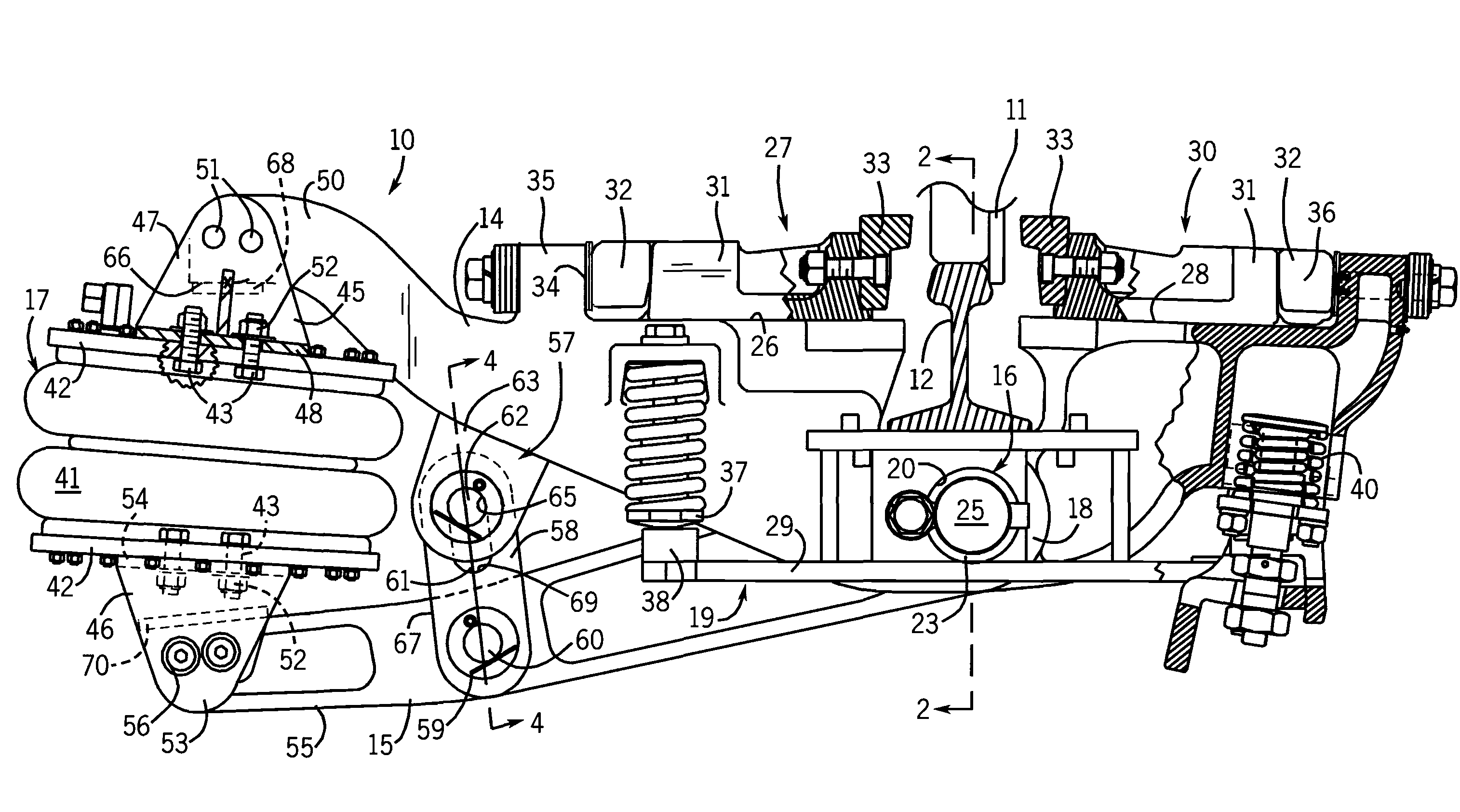
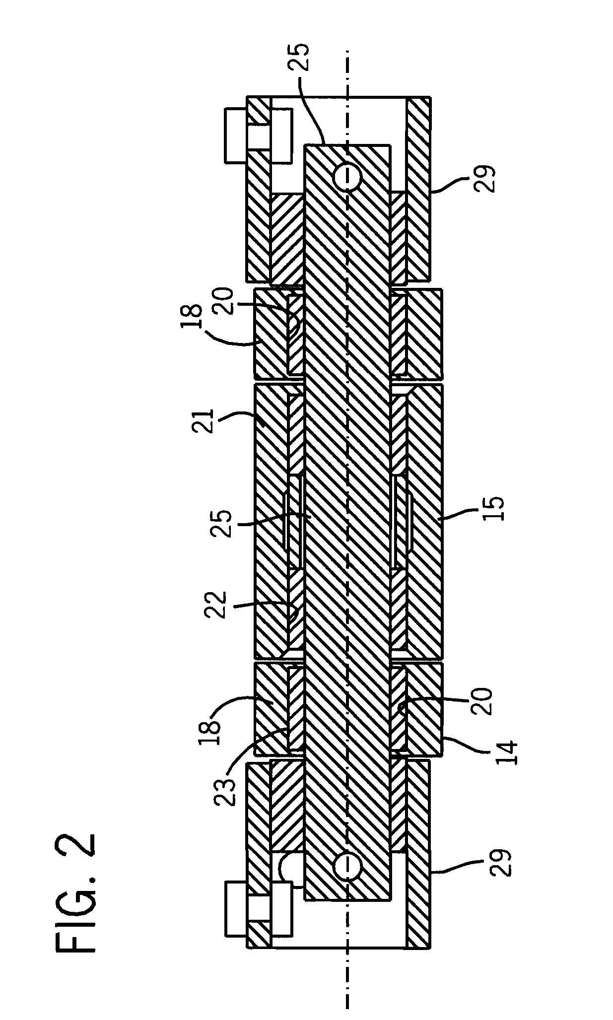
[0011]In accordance with the present invention, a bladder actuated retarder for a rail car includes a stroke limiter linkage assembly, the change in position of which can be monitored to provide an accurate indication of fulcrum bearing wear. The invention is applied to a conventional retarder apparatus including an upper lever arm that is pivotally connected to a lower lever arm with a fulcrum pin assembly. The fulcrum pin assembly includes a pin carried in a cylindrical bearing and rotatable therein. The lever arms have opposed ends to each of which is connected an end of an extensible bladder actuator that is operative to cause relative rotation of the lever arms on the fulcrum pin and to move the opposed ends of the arms apart. In accordance with the present invention, the actuator stroke limiter linkage assembly interconnects the lever arms at a location between the arms and between the fulcrum pin and the actuator to prevent extension of the actuator beyond a desired limit. The stroke limiter assembly is also operative to limit compression of the bladder actuator beyond the limit of collapse recommended by the manufacturer.
[0017]In a further embodiment of the invention, the air bladder actuator comprises an expandable rubber bladder member, a pair of rigid end plates that enclose opposite ends of the bladder member with air-tight seals, and mounting brackets that provide rigid connections between the end plates and the opposed ends of the lever arms. The end plates are oriented, in use, to diverge in a direction away from the fulcrum pin in the extended position of the bladder and to move through a neutral position to a position in which the end plates converge in the direction away from the fulcrum pin, whereby lateral deflection of the bladder member is balanced and minimized.

Problems solved by technology

The railroad marshalling yard environment is dirty, rugged and non-stop.
A problem with railroad retarders is reducing maintenance to meet the demands of a busy marshalling yard setting.
Evaluating fulcrum bearing wear is particularly problematic because the bearing is enclosed in the retarder.
Because closing a portion of the yard is impractical in a busy yard, maintenance personnel resort to using a pry bar to physically pry apart the upper and lower lever arms to determine if there is any wiggle occurring at the fulcrum bearing.
Yet, this “wiggle” test is unreliable, particularly when done by a worker who is not familiar with the internal structure and mechanics of the retarder, and is not aware of the likely wear locations of the fulcrum bearing.
If the pry bar is not inserted into the retarder and pushed or pulled in directions that will reveal the actual amount of wear, then the test may incorrectly indicate that little or no wear has occurred.
Yet, a lack of proper inspection can result in an untimely failure of the fulcrum and retarder, which will then need to be replaced.
Replacing a retarder is difficult to schedule because it requires a portion of the yard to be closed, which adversely impacts yard usage.
Replacing a retarder during winter months when the ground is frozen is impractical.
The longer the workers are close to or in physical contact with the retarder, the more likely they are to be injured due to the daily risks associated with yard work.
Inspecting bearing wear places workers at risk because the “wiggle” test requires a worker to stand on or near the retarder to manipulate the pry bar.
The test is also inherently dangerous because of the awkward position and significant force a person must exert with the pry bar.
Disassembling the retarder to inspect the bearing is even more involved, more time consuming, and more of a safety concern for the workers.
Another problem with conventional air bladder retarders is air consumption.
The compressed air supply system for the yard has limited capacity.
Installing numerous air bladder retarders throughout the yard can significantly increase yard air consumption.
Yet, modifying or replacing the yard compressed air supply system is costly and time consuming, particularly regarding yard down time.
Another problem with air bladder retarders is life expectancy.
Any crimping of the bladder during use can cause accelerated wear on the inside surface of the bladder.
This wear weakens the bladder and can lead to premature rupturing.
This problem is accentuated when the upper and lower plates of the bladder are pivotally connected to the lever arms by pivot pins.
The pivot connections allow the plates to rotate, which can lead to undesired crimping.
Another problem with conventional air bladder retarders is predictable use and service requirements.
A problem with using an air bladder as an actuator for a railroad retarder is that it is difficult to identify or measure the wear on the bladder such as internal wear caused by crimping.
Disassembling the actuator to inspect the bladder involves safety risks, maintenance costs and yard down time.
Still, even a small leak in the bladder will waist yard air.
Any unpredicted, premature rupture of the bladder will disable the retarder, lead to unplanned and costly replacement and down time, and increase safety risks to yard maintenance personnel.
Another problem with bladder actuators is the design of the guide mechanism.
Yet, maintaining the alignment of the guide rod is critical.
Even a slight loosening of the guide rod can result in some lateral movement, which will exponentially increase the loads on and wear rate of the internal bushing or bearing.
This loosening of the guide rod, or even the potential loosening of the guide rod, significantly increases the need for routine maintenance and possible down time.
This construction can lead to crimping of the bladder, and result in leaks and unpredicted rupture of the bladder.

Method used


Image

  • Bladder-actuated railroad retarder
  • Bladder-actuated railroad retarder
  • Bladder-actuated railroad retarder

Examples


Embodiment Construction

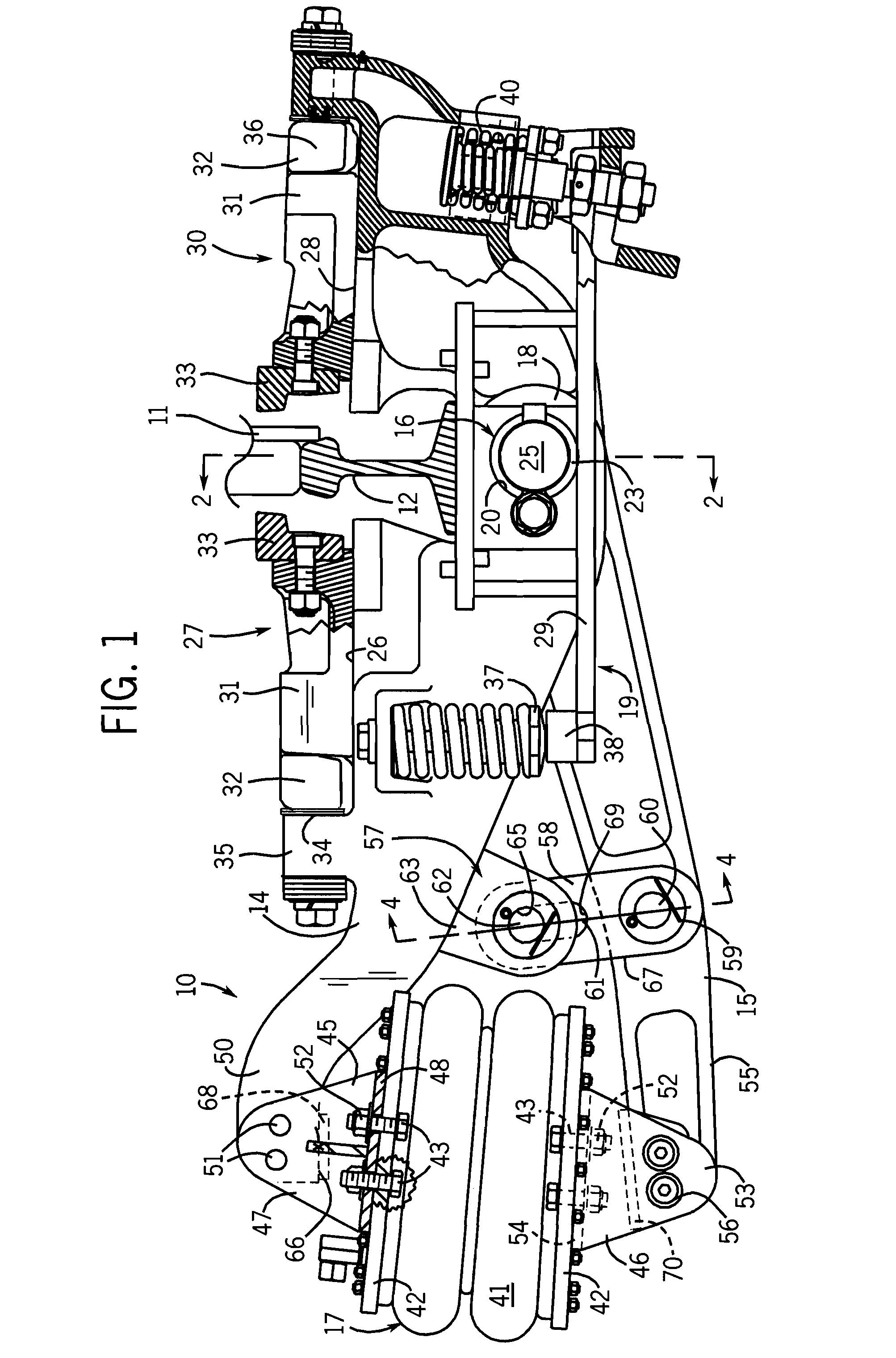
[0027]Referring initially to FIGS. 1 and 7, a pneumatic retarder 10 of the present invention is used to control the speed of a moving car in a marshalling yard by engaging opposite faces of a car wheel 11 as it rolls on a rail 12 through the retarder. The retarder 10 is positioned between adjacent ties and extends beneath the rail 12 from an outer field side of the rail to an inner cage side between the rails 12 (only one of which is shown in the drawings). A support structure 19 for the retarder includes substantially identical supports 29 carried by the ties and positioned in opposite sides of the retarder.

[0028]The retarder 10 has an upper lever arm 14 and a lower lever arm 15 which are pivotally connected with a fulcrum pin assembly 16 positioned directly beneath the rail 12. On the field side of the retarder, the lever arms 14 and 15 have opposed ends to each of which is attached an end of an air bladder actuator 17. The fulcrum end of the upper lever arm 14 has a bifurcated co...


PUM


Abstract

An air bladder actuated railroad car retarder is designed to simplify installation, operate in a manner imposing minimal stress on the bladder, improve preventive maintenance, and simplify access to the main fulcrum bearings. The air bladder actuator is made with lightweight aluminum end plates and utilizes a unique stud assembly for attaching the actuator to the retarder pivot arms. Rigid mounting of the air bladder with a unique pivot geometry exposes the bladder to minimal lateral deflection which is balanced in both directions. A simple stroke limiter assembly, external to the air bladder, is also used to measure and monitor wear of the main fulcrum bearings. The stroke limiter assembly is easily demountable and removable to enhance access to the main fulcrum pivot for replacement of the fulcrum bearings.

Description

BACKGROUND OF THE INVENTION[0001]The present invention relates to a bladder-actuated low-profile railroad retarder that is particularly suited for a railroad marshalling yard.[0002]Bladder actuators are well known in the railroad industry. In 1882, the Smith Vacuum Brake included a sack or collapsing cylinder. The Firestone AIRSTROKE actuator developed in the 1930s includes upper and lower plates and a flexible bladder secured around the perimeter of each plate to form an airtight interior. The actuator is inflated and deflated to control its height. Down and up stops are used to set the minimum and maximum height or stroke length (SL) of the actuator. A bumper, a chain, a cable or metal stops can be located inside the actuator for this purpose. U.S. Reissue Pat. No. Re 33,207 discloses an on-board braking system using the Firestone actuator. U.S. Pat. No. 6,220,400 discloses a low profile, railway car retarder using the Firestone actuator. The actuator has an internal guide formed ...

Claims


Application Information

Patent Timeline
Patent Type & Authority Applications(United States)
IPC IPC(8): B60T11/10B61H11/00
CPCB61K7/08F16D2121/12F16D63/00
Inventor HEYDEN, THOMAS J.
Owner PRECISION RAIL & MFG
Learn More