Eureka AIR delivers breakthrough ideas for toughest innovation challenges, trusted by R&D personnel around the world.

Ink jet printing apparatus and ink jet printing method

Inactive Publication Date: 2009-02-19
CANON KK
View PDF9 Cites 8 Cited by
  • Summary
  • Abstract
  • Description
  • Claims
  • Application Information

AI Technical Summary

Benefits of technology

[0028]The present invention has been accomplished to overcome the problems described above. It is therefore an object of this invention to provide an ink jet printing apparatus that can produce an image with an appropriate balance of image quality and printing speed, without unduly shortening the life of a print head, even if an odd-numbered-pass printing is performed.

Problems solved by technology

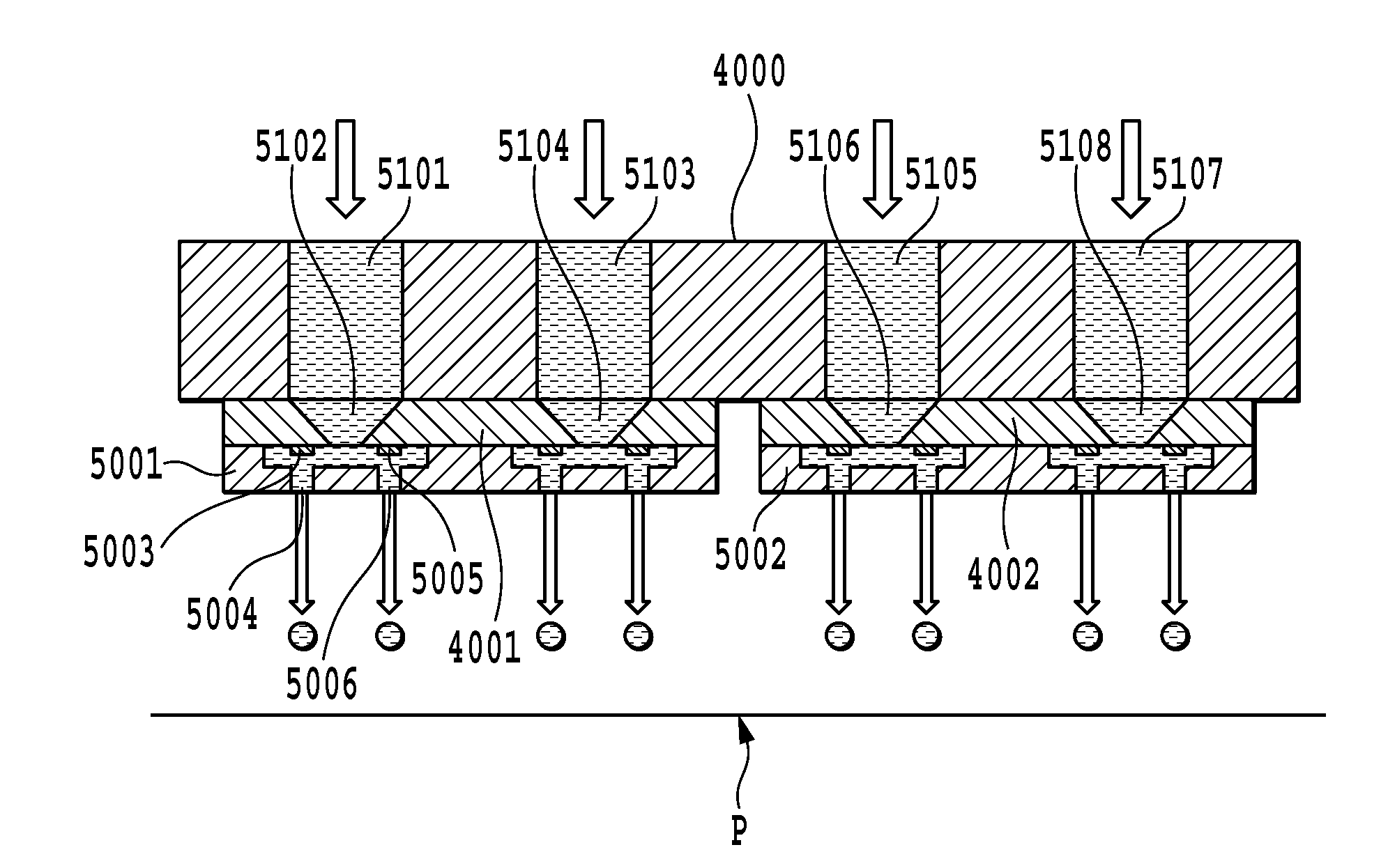
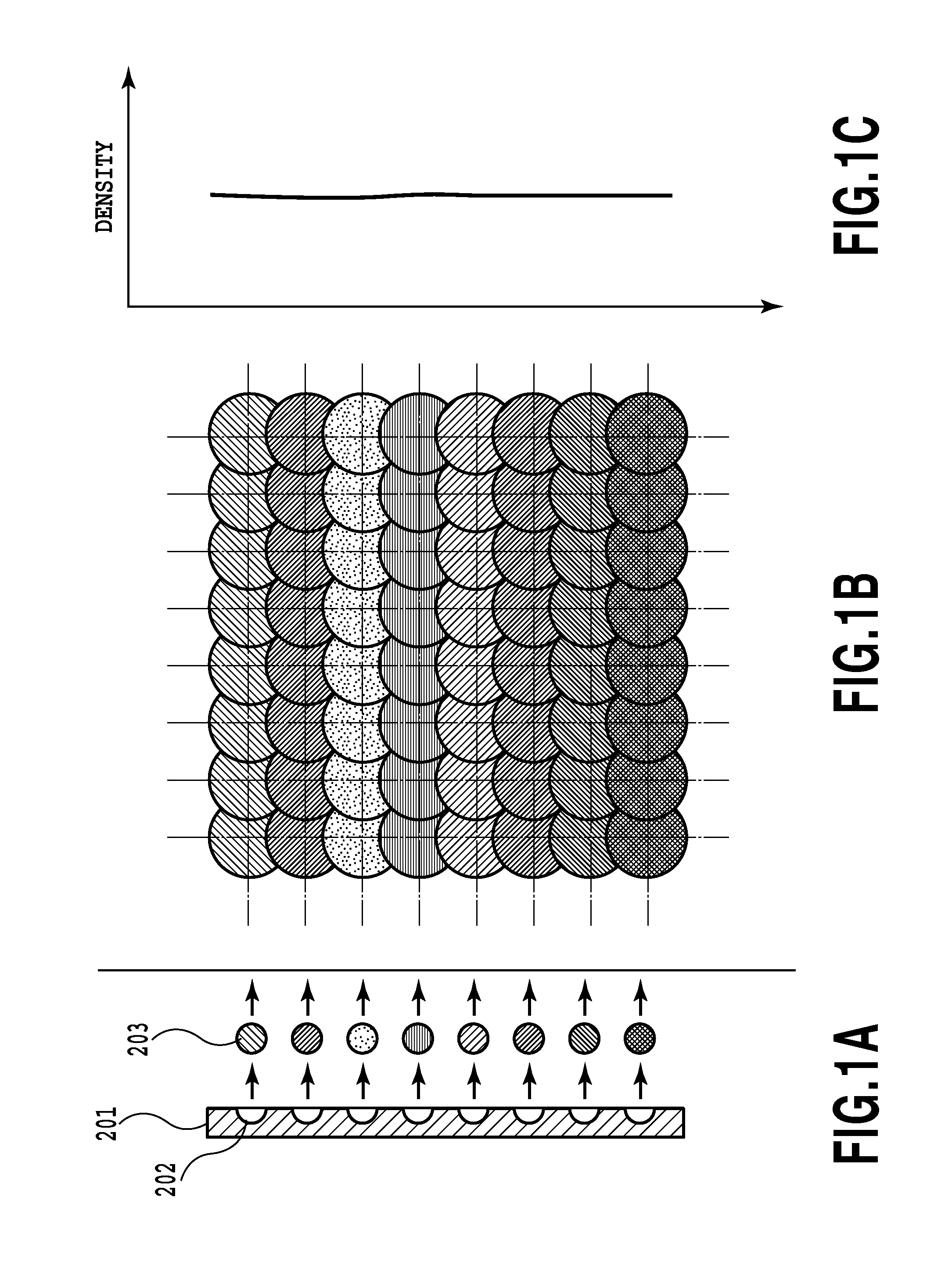
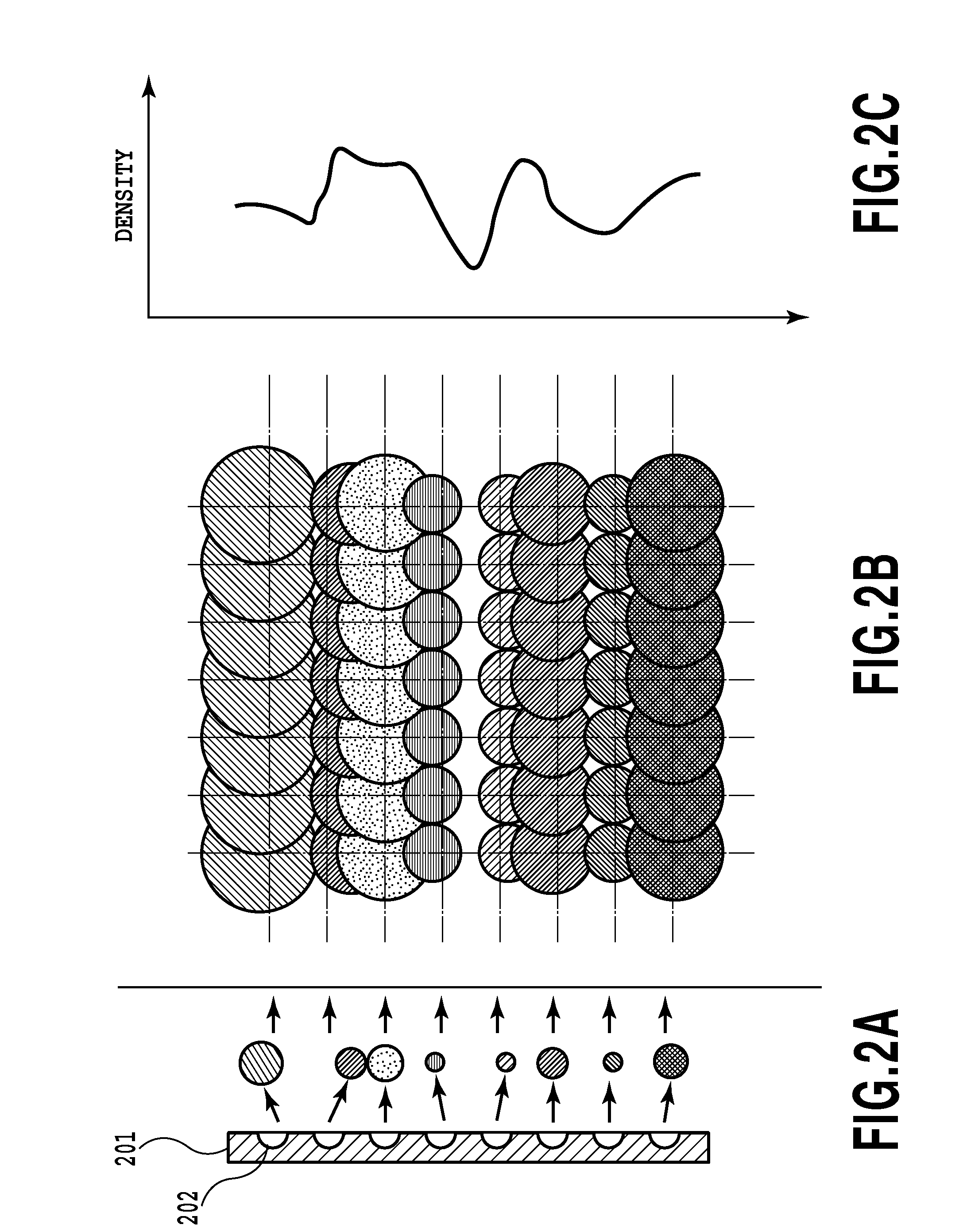
These variations influence the ejection volume and direction of ink ejected from the nozzles, which in turn generates density unevenness and stripes in an image formed on a print medium.
An increase in the number of passes, however, results in a reduction in the printing speed.
It should, however, be noted that when a bidirectional multi-pass printing is performed using an odd number of passes in, a new problem that does not emerge in a multi-pass printing with an even number of passes arises.
At this time, even if the plurality of ink colors are ejected in the same percentages in both the opposite scans to produce the same image colors, there inevitably occurs some color difference between an image obtained in the forward scan and an image obtained in the backward scan.
Since colors and densities may differ between these two kinds of image areas, overall image impairments such as color unevenness and density unevenness are likely to occur.
That is, the use of the stepping mask may pose a risk of eliminating the advantage the multi-pass printing is intended to produce—that of “alleviating the adverse effect of image due to ejection characteristics of individual nozzles”.
Another problem in using the stepping mask is that the print head longevity may be reduced by a shortened life of a nozzle having a high frequency of use.

Method used


Image

  • Ink jet printing apparatus and ink jet printing method
  • Ink jet printing apparatus and ink jet printing method
  • Ink jet printing apparatus and ink jet printing method

Examples


first embodiment

[0053]FIG. 8 is a block diagram showing a control construction of printing system which includes a printing apparatus 200 and an information processing device (host computer) 100 in this embodiment. Denoted 200 is an ink jet printing apparatus that ejects ink from a print head to perform printing. Designated 100 is an information processing device that has functions of supplying image data to the ink jet printing apparatus 200 and controlling it. The printing apparatus 200 and the information processing device 100 are connected to a known communication means (interface) for mutual communication. The information processing device 100, according to instructions from the user, generates image data to be supplied to the printing apparatus 200 and causes the printing apparatus 200 to execute a printing operation based on the image data. By using the information processing device, user can select one print mode from a plurality of print mode which can be performed in the printing apparatu...

second embodiment

[0078]Next, a second embodiment of this invention will be described. The second embodiment is characterized in that it uses a stepping mask for a 3-pass printing different from the one used in the first embodiment. As for the construction of the printing apparatus, it is the same as that of the first embodiment and therefore its explanation is omitted here.

[0079]In the first embodiment, an example stepping mask has been described, by referring to FIG. 6, to make the sum of print permitted ratios for forward scans and the sum of print permitted ratios for backward scans equal at 50%. The stepping mask the second embodiment can adopt, however, is not limited to such a configuration. If, as described in the first embodiment, a difference in print permitted ratio between forward scans and backward scans is less than 20% and there is no concern for the image problem described above, a mask pattern may be used that is already adjusted in print permitted ratio to suppress the print permitt...

third embodiment

[0081]In the first embodiment and second embodiment, a stepping mask is used for a 3-pass print mode and a flat mask is used for a 5-pass or a 7-pass print mode. However, this invention is not limited to this configuration. For example, stepping masks can be used for a 3-pass and for a 5-pass print modes and a flat mask can be used for a 7-pass print mode. The third embodiment is characterized by using a stepping mask for a 5-pass print mode. As for the construction of the printing apparatus, it is the same as that of the first embodiment and therefore its explanation is omitted here.

[0082]FIG. 18 shows an example of mask pattern used for a 5-pass printing. Five divided blocks of a nozzle array are shown to be assigned mask patterns of 16%, 25%, 18%, 25% and 18%, from one end to the other. In this mask pattern, a difference between maximum value and minimum value of the print permitted ratio among multiple scans is set to 9% (=25%-18%). In addition, both of a sum of the print permit...


PUM


Abstract

An ink jet printing apparatus is provided which is capable of producing an image with a good balance between image quality and printing speed, without unduly shortening a longevity of a print head, even when an odd-numbered-pass bidirectional printing is performed. To this end, during a bidirectional multi-pass printing with a relatively small number of passes, a stepping mask is used to eliminate image problems caused by a difference in print permitted ratio between forward scan and backward scan. During a bidirectional multi-pass printing with a relatively large number of passes, a flat mask is used to give priority to suppressing density unevenness resulting from nozzle characteristic variations. As a result, the printing apparatus as a whole can produce an image with a good balance between image quality and printing speed, without unduly shortening a longevity of the print head.

Description

BACKGROUND OF THE INVENTION[0001]1. Field of the Invention[0002]The present invention relates to an ink jet printing apparatus and an ink jet printing method. More specifically it relates to a multi-pass printing method commonly employed in serial type printing apparatus.[0003]2. Description of the Related Art[0004]In recent years, relatively inexpensive office automation devices such as personal computers and word processors have come into widespread use. At the same time, efforts are being made to develop various types of printing apparatus that output information supplied from these devices and to enhance printing speed and print quality of these printing apparatus. Among others, a serial type ink jet printing apparatus is drawing attention as a relatively small printing apparatus capable of producing prints at low cost at high speed or with high quality. Such a serial type ink jet printing apparatus can perform a bidirectional printing to produce an image at high speed or perfor...

Claims


Application Information

Patent Timeline
IPC IPC(8): B41J2/145
CPCB41J19/147
Inventor EDAMURA, TETSUYATAKAHASHI, KIICHIROTESHIGAWARA, MINORUMARU, AKIKOMURAYAMA, YOSHIAKINAKANO, TAKATOSHITAIRA, HIROSHI
Owner CANON KK
Why Eureka
Eureka Blog
Learn More